Features
With this module you can communicate with LoRa and locate yourself with GNSS. It integrates a LoRa E80-900M2213S (LR1121) module from Ebyte and a GNSS MAX-M10S module from U-Blox. We are working on the integration with Meshtastic.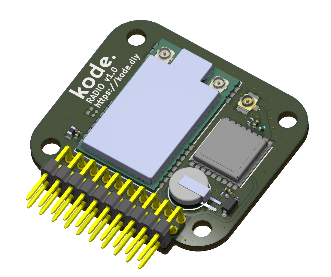
Connection with the Kode Dot
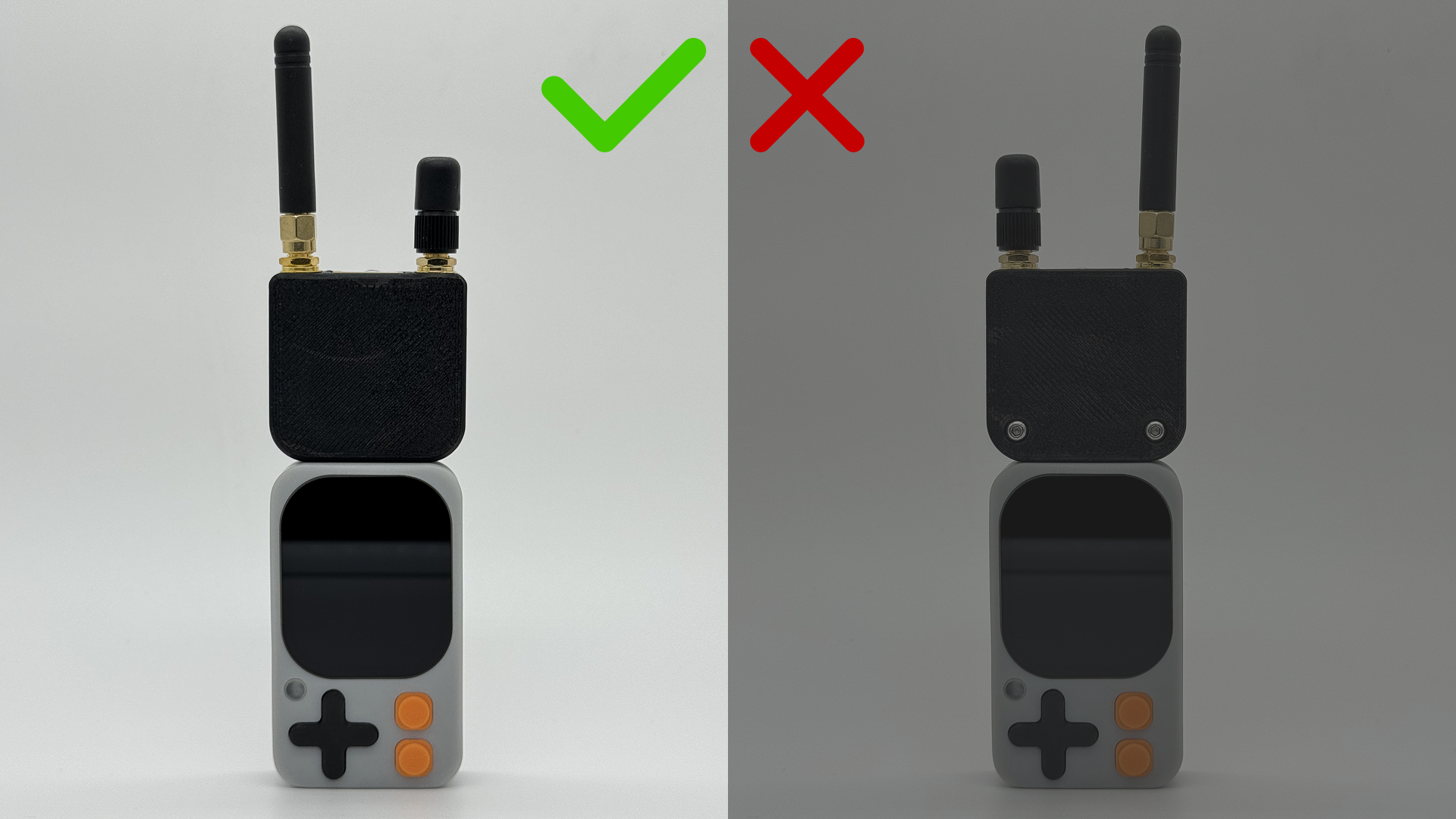
Connection scheme
LoRa module
The Ebyte E80-900M2213S module is connected to the ESP32-S3 as follows:| E80-900M2213S | ESP32-S3 |
|---|---|
| MISO | GPIO41 |
| MOSI | GPIO40 |
| SCK | GPIO39 |
| NSS (CS) | GPIO3 |
| BUSY | GPIO13 |
| LR_NRESET | GPIO2 |
| DIO9 | GPIO12 |
| DIO8 | GPIO1 |
| DIO7 | GPIO11 |
GNSS module
The GNSS MAX-M10S module is connected to the ESP32-S3 as follows:| MAX-M10S | ESP32-S3 |
|---|---|
| TXD | GPIO44 |
| RXD | GPIO43 |
| SCL | GPIO47 |
| SDA | GPIO48 |
Code examples
Communication with LoRa
lora_test.ino
/**
 * LR1121 Channel Scanner (RX only, no TX).
 * Scans 868 MHz and 2.4 GHz bands with dynamic BW and SF changes.
 * Measures RSSI (channel noise) and prints results in CSV format.
 */
/* ───────── KODE | docs.kode.diy ───────── */

#include <Arduino.h>
#include <RadioLib.h>

/* Pin configuration (based on your design) */
#define NSS_PIN    3    /* Chip Select */
#define DIO1_PIN   12   /* IRQ */
#define NRST_PIN   2    /* Reset */
#define BUSY_PIN   13   /* Busy */
#define MISO_PIN   41
#define MOSI_PIN   40
#define SCK_PIN    39

/* RF Switch mapping for E80-900M2213S */
static const uint32_t rfswitch_dio_pins[] = {
  RADIOLIB_LR11X0_DIO5, RADIOLIB_LR11X0_DIO6,
  RADIOLIB_NC, RADIOLIB_NC, RADIOLIB_NC
};
static const Module::RfSwitchMode_t rfswitch_table[] = {
  { LR11x0::MODE_STBY,  { LOW,  LOW  } },
  { LR11x0::MODE_RX,    { LOW,  LOW  } },  /* RX */
  { LR11x0::MODE_TX,    { LOW,  HIGH } },  /* TX Sub-1GHz LP */
  { LR11x0::MODE_TX_HP, { HIGH, LOW  } },  /* TX Sub-1GHz HP */
  { LR11x0::MODE_TX_HF, { HIGH, HIGH } },  /* TX 2.4GHz */
  { LR11x0::MODE_GNSS,  { LOW,  LOW  } },
  { LR11x0::MODE_WIFI,  { LOW,  LOW  } },
  END_OF_MODE_TABLE,
};

/* Instances */
SPIClass spi(HSPI);
LR1121 radio = new Module(NSS_PIN, DIO1_PIN, NRST_PIN, BUSY_PIN, spi);

/* Frequency sweep settings */
const float FREQS_868[] = { 863.0, 866.0, 868.0, 869.5 };
const float FREQS_24[]  = { 2403.5, 2425.0, 2450.0, 2479.5 };
const size_t N_868 = sizeof(FREQS_868) / sizeof(FREQS_868[0]);
const size_t N_24  = sizeof(FREQS_24)  / sizeof(FREQS_24[0]);

/* Dynamic parameters */
const float  BWS_KHZ[] = { 125.0, 203.125 };
const int    SFS[]     = { 7, 9, 12 };
const int    CR        = 5;
const int    PWR_DBM   = 10;
const uint8_t PREAMBLE = 8;
const float  TCXO_V    = 1.8;

/* Listening time per measurement point */
const uint16_t DWELL_MS = 200;

/* Utilities */
/* Hardware reset for LR1121 */
static void hardResetModule() {
  pinMode(NRST_PIN, OUTPUT);
  digitalWrite(NRST_PIN, LOW);
  delay(50);
  digitalWrite(NRST_PIN, HIGH);
  delay(50);
}

/* Configure LR1121 with given parameters */
static bool configRadio(float freqMHz, float bwkHz, int sf) {
  int st = radio.begin(freqMHz, bwkHz, sf, CR, 0x12 /*sync*/, PWR_DBM, PREAMBLE, TCXO_V);
  if (st != RADIOLIB_ERR_NONE) {
    Serial.print("Config FAIL  f="); Serial.print(freqMHz, 3);
    Serial.print(" MHz  BW="); Serial.print(bwkHz, 3);
    Serial.print(" kHz  SF="); Serial.print(sf);
    Serial.print("  code="); Serial.println(st);
    return false;
  }
  return true;
}

/* Measure RSSI once at given parameters and print CSV line */
static void measureOnce(float freqMHz, float bwkHz, int sf, const char* bandTag) {
  if (!configRadio(freqMHz, bwkHz, sf)) return;

  /* Start RX */
  int st = radio.startReceive();
  if (st != RADIOLIB_ERR_NONE) {
    Serial.print("RX start FAIL code="); Serial.println(st);
    return;
  }

  delay(DWELL_MS);
  float rssi = radio.getRSSI();

  /* CSV format output: BAND,FREQ_MHz,BW_kHz,SF,RSSI_dBm */
  Serial.print(bandTag); Serial.print(",");
  Serial.print(freqMHz, 3); Serial.print(",");
  Serial.print(bwkHz, 3); Serial.print(",");
  Serial.print(sf); Serial.print(",");
  Serial.println(rssi, 1);

  radio.standby();
}

/* Scan a full band across frequencies, BWs and SFs */
static void scanBand(const float* freqs, size_t nFreq, const char* bandTag) {
  Serial.println();
  Serial.println("BAND,FREQ_MHz,BW_kHz,SF,RSSI_dBm");
  for (size_t i = 0; i < nFreq; i++) {
    for (size_t b = 0; b < sizeof(BWS_KHZ)/sizeof(BWS_KHZ[0]); b++) {
      for (size_t s = 0; s < sizeof(SFS)/sizeof(SFS[0]); s++) {
        measureOnce(freqs[i], BWS_KHZ[b], SFS[s], bandTag);
      }
    }
  }
}

/* Setup */
void setup() {
  Serial.begin(115200);
  while (!Serial) { delay(10); }
  Serial.println("\n=== LR1121 Channel Scanner (RSSI only) ===");
  Serial.println("RSSI = channel noise (closer to 0 => more noise)");

  pinMode(BUSY_PIN, INPUT);

  Serial.println("Resetting module...");
  hardResetModule();

  Serial.println("Initializing SPI...");
  spi.begin(SCK_PIN, MISO_PIN, MOSI_PIN, NSS_PIN);

  radio.setRfSwitchTable(rfswitch_dio_pins, rfswitch_table);

  Serial.println("\n--- Scanning: 868 MHz ---");
  scanBand(FREQS_868, N_868, "868MHz");

  Serial.println("\n--- Scanning: 2.4 GHz ---");
  scanBand(FREQS_24, N_24, "2400MHz");

  Serial.println("\nScan complete. Restart to repeat.");
}

/* Loop */
void loop() {
  delay(1000);
}
Location with GNSS
For using the GNSS module, we recommend using the library SparkFun u-blox GNSSUse by I2C
This code is an example of how to use the GNSS module via I2C.gnss_test_I2C.ino
/**
 * Example: Reading GNSS (GPS) data from a Kode Radio Module via I2C.
 * Retrieves latitude, longitude, and altitude from the u-blox module.
 * Uses the PVT (Position, Velocity, Time) message for data retrieval.
 */
/* ───────── KODE | docs.kode.diy ───────── */

#include <SparkFun_u-blox_GNSS_v3.h>
#include <Wire.h>

/* GNSS module object */
SFE_UBLOX_GNSS myGNSS;

void setup()
{
  Serial.begin(115200);
  delay(1000);
  Serial.println("Kode Radio Module Example");

  /* ─── Initialize I2C with SDA = GPIO48, SCL = GPIO47 ─── */
  Wire.begin(48, 47);

  /* Enable GNSS debug messages on Serial (optional) */
  myGNSS.enableDebugging(); // Comment this line to disable debug messages

  /* Try to connect to the u-blox GNSS module until successful */
  while (myGNSS.begin() == false)
  {
    Serial.println(F("u-blox GNSS not detected. Retrying..."));
    delay(1000);
  }

  /* Set I2C output to UBX protocol only (disable NMEA messages) */
  myGNSS.setI2COutput(COM_TYPE_UBX);
}

void loop()
{
  /* If PVT data is available, read and display it */
  if (myGNSS.getPVT() == true)
  {
    /* Get and print latitude */
    int32_t latitude = myGNSS.getLatitude();
    Serial.print(F("Lat: "));
    Serial.print(latitude);

    /* Get and print longitude */
    int32_t longitude = myGNSS.getLongitude();
    Serial.print(F(" Long: "));
    Serial.print(longitude);
    Serial.print(F(" (degrees * 10^-7)"));

    /* Get and print altitude (MSL) */
    int32_t altitude = myGNSS.getAltitudeMSL();
    Serial.print(F(" Alt: "));
    Serial.print(altitude);
    Serial.print(F(" (mm)"));

    Serial.println();
  }
}
Use by UART
This code is an example of how to use the GNSS module via UART.gnss_test_UART.ino
#include <SparkFun_u-blox_GNSS_v3.h>

/* GNSS object for serial communication */
SFE_UBLOX_GNSS_SERIAL myGNSS;

/* ─── GNSS UART pin mapping ───
 * GNSS_RX_PIN → MCU pin that receives data from GNSS TX
 * GNSS_TX_PIN → MCU pin that sends data to GNSS RX
 */
static const int GNSS_RX_PIN = 44; // MCU receives on GPIO44
static const int GNSS_TX_PIN = 43; // MCU transmits on GPIO43

/* Hardware serial instance (UART1) */
HardwareSerial GNSSSerial(1);

void setup()
{
  Serial.begin(115200);
  delay(1000);
  Serial.println("u-blox GNSS via UART1 (GPIO44/43)");

  /* ─── Initialize UART1 on the specified pins ───
   * Baud rate: 38400
   * Format: 8 data bits, no parity, 1 stop bit (SERIAL_8N1)
   */
  GNSSSerial.begin(38400, SERIAL_8N1, GNSS_RX_PIN, GNSS_TX_PIN);

  /* Enable GNSS debug messages on main Serial (optional) */
  myGNSS.enableDebugging(Serial);

  /* Configure UART1 output → UBX protocol only (disable NMEA messages) */
  myGNSS.setUART1Output(COM_TYPE_UBX);

  /* Attempt to connect to the GNSS module until successful */
  while (!myGNSS.begin(GNSSSerial)) {
    Serial.println(F("u-blox GNSS not detected. Retrying..."));
    delay(1000);
  }
}

void loop()
{
  /* If PVT (Position, Velocity, Time) data is available, read and display it */
  if (myGNSS.getPVT()) {
    int32_t lat = myGNSS.getLatitude();      // Latitude in degrees * 10^-7
    int32_t lon = myGNSS.getLongitude();     // Longitude in degrees * 10^-7
    int32_t alt = myGNSS.getAltitudeMSL();   // Altitude MSL in millimeters

    Serial.print(F("Lat: ")); Serial.print(lat);
    Serial.print(F(" Long: ")); Serial.print(lon);
    Serial.print(F(" (deg*1e-7) Alt: ")); Serial.print(alt);
    Serial.println(F(" (mm)"));
  }
}