Modules
Robotics
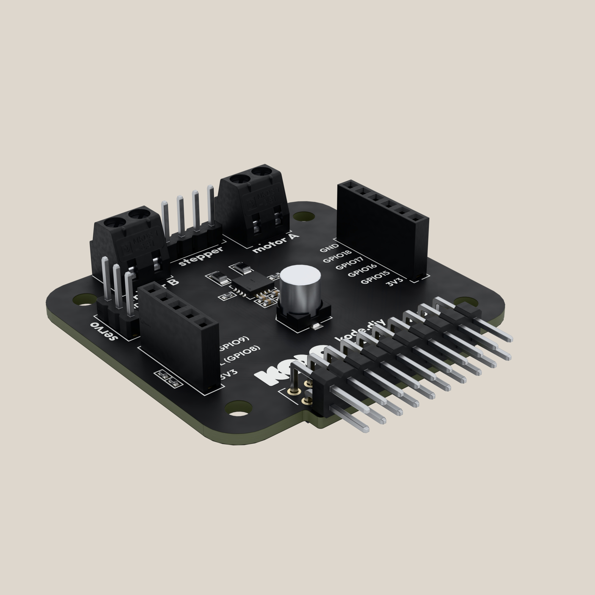
Two DC motors, a servo, an I2C port and four pins for sensors: the module for a robot with the Kode Dot as its brain.
What it is
The Robotics module drives a robot with the Kode Dot as its brain. What you can connect:
- 2 DC motors, on two screw terminals, with a limit of about 0.4 A each.
- 1 servo, on a three-pin header.
- 1 I2C sensor, such as a distance sensor or a small display, on its own port.
- 4 GPIOs for line sensors or encoders, three of them analog.
Everything runs from the Kode Dot's 5 V, which come straight from the USB cable. With the cable in, you get what your charger gives, up to the header's 2 A fuse. A computer's USB port gives 0.5–0.9 A. On battery, the SDK's boost gives 0.5 A, little for two motors and a servo. The motors are driven by an AT8833CQ, a dual H-bridge.
How it is connected
The module plugs straight into the 20-pin header and stands upright on the top edge.
- Push the module's pins into the header, with the chip facing the same way as the screen.
- Connect each motor to its terminal,
J501for A andJ502for B. The servo goes on the three-pin header, with its ground wire on pin 1. - Leave the USB cable in and open your app for the module. On battery, the motors turn only if the app asks for the 5 V boost.
The I2C port is a bus of its own on GPIO8 and GPIO9, with pull-ups on the module. The Kode Dot's internal I2C bus, on GPIO4 and GPIO5, does not reach the header.
Specifications
| Thing | Value |
|---|---|
| Part | KDROB001, revision 1.0, issue of 2026-10-26. Same circuit as the 2026-10-07 issue; black solder mask and production part numbers for the connectors and the bulk capacitor |
| Mounts on | The Kode Dot's 20-pin header, straight |
| Which way | The GPIOs in this table are for the module with its components on the screen side. Turned round, the connector fits too and the signal of header position p arrives on position 15 − p: SCL on GPIO16, SDA on GPIO15, the servo on GPIO17, nFAULT on GPIO20, BIN1 on GPIO19, BIN2 on GPIO21, AIN2 on GPIO14, nSLEEP on GPIO13, AIN1 on GPIO12, the sensor header on GPIO9, GPIO8, GPIO11 and GPIO10, and the I2C port's spare line on GPIO18. Kode's factory bench tests the module that way round, and Kode's Robotics SDK ran the motors and the servo both ways on a Kode Dot on 2026-10-27 |
| Driver | AT8833CQ, dual H-bridge, with the motor supply on the Kode Dot's 5 V |
| Motor A | Terminal J501: AOUT1, AOUT2. Inputs AIN1 = GPIO20, AIN2 = GPIO21 |
| Motor B | Terminal J502: BOUT1, BOUT2. Inputs BIN1 = GPIO13, BIN2 = GPIO14 |
| PWM | 20 kHz, the frequency of Kode's test program. Hold one input high and pulse the other: the bridge brakes between pulses and speed follows the duty cycle |
| Current limit | 0.4 A per motor: 200 mV across a 0.5 Ω sense resistor, R504 for A and R503 for B. With the datasheet's tolerance, 0.32–0.48 A. TBD: the limit measured on a board |
| Overcurrent trip | 2.2–3 A, apart from the limit. The driver shuts down and retries about every 1.9 ms |
| Sleep | nSLEEP = GPIO19, 10 kΩ pull-up. Low puts the driver to sleep |
| Fault | nFAULT = GPIO12, 10 kΩ pull-up. Low means the driver tripped on overcurrent or overtemperature. A trip repeats, so the line pulses |
| Servo header | J402, 3 pins: GND · 5 V · signal on GPIO11. The servo takes the 5 V straight, with no limit of its own |
| I2C port | J403, 5 pins: GND · GPIO10 · SDA GPIO9 · SCL GPIO8 · 3.3 V. 2.2 kΩ pull-ups on the module |
| Sensor header | J404, 6 pins: 3.3 V · GPIO15 · GPIO16 · GPIO17 · GPIO18 · GND. GPIO16, GPIO17 and GPIO18 read analog |
| Pin header | J503, 4 pins: the same four motor outputs as the terminals, for a Dupont cable. Marked stepper. A NEMA 17 bipolar stepper ran from it in half steps from a Kode Dot on 2026-10-15, on the header's 5 V and within the bridge's current limit |
| Power | Motors and servo on the Kode Dot's 5 V, with no input of their own. On USB, a 2 A fuse, 1.5 A with the case warm (device/expansion). On battery, off until the firmware asks for the boost, which gives 0.5 A (device/power) |
| Validated | Motors A and B both ways, the servo, the I2C port, the module turned round, and unplugging it and plugging it back, with Kode's Robotics SDK on a Kode Dot running kodeOS v00.00.24, 2026-10-27. Before that, one motor both ways and nFAULT clean on a first prototype with the driver replaced, 2026-09-16 (Kode-Dot-Val/2-DVT/14-EXPANSION/robotics_module). TBD: the same on the 2026-10-26 issue |
Gotchas
Example code
Drives motor A forward at half speed, with the Kode Dot on USB. The motor on terminal A turns and keeps turning.
/*
 * robotics_motor.c - 2026-10-14 - from Kode with love
 *
 * Drives motor A of the Robotics module at half speed, with the Kode Dot on
 * USB. Wakes the driver, holds AIN1 high and pulses AIN2 at 20 kHz: the
 * bridge brakes while AIN2 is high, so half the width is half the speed.
 * The motor on terminal A turns and keeps turning.
 */
#include "driver/gpio.h"
#include "driver/ledc.h"

#define MOTOR_SLEEP  GPIO_NUM_19   /* nSLEEP: high keeps the driver awake */
#define MOTOR_A_IN1  GPIO_NUM_20
#define MOTOR_A_IN2  GPIO_NUM_21

/* Wakes the driver, holds AIN1 high and pulses AIN2: braking between pulses. */
void app_main(void)
{
    gpio_set_direction(MOTOR_A_IN1, GPIO_MODE_OUTPUT);
    gpio_set_level(MOTOR_A_IN1, 1);
    gpio_set_direction(MOTOR_SLEEP, GPIO_MODE_OUTPUT);
    gpio_set_level(MOTOR_SLEEP, 1);

    ledc_timer_config_t timer = {
        .speed_mode = LEDC_LOW_SPEED_MODE,
        .timer_num = LEDC_TIMER_1,
        .duty_resolution = LEDC_TIMER_10_BIT,
        .freq_hz = 20000,                  /* above hearing */
    };
    ledc_timer_config(&timer);

    ledc_channel_config_t channel = {
        .speed_mode = LEDC_LOW_SPEED_MODE,
        .channel = LEDC_CHANNEL_1,
        .timer_sel = LEDC_TIMER_1,
        .gpio_num = MOTOR_A_IN2,
        .duty = 512,                       /* 50 % of 10 bits: half of each pulse is braking */
    };
    ledc_channel_config(&channel);
}
Compiled on the date in the header with ESP-IDF v6.1. TBD: a run of this program on a board. Kode's validation program, robotics_module in Kode-Dot-Val/2-DVT/14-EXPANSION, drives both motors and the servo from a console over USB.
In the SDK
kode.h: in a kodeOS app,kode_exp_power(true)switches the header's 3.3 V on,kode_exp_lend()takes the module's positions under a name and gives you their GPIO numbers,kode_exp_ctrl()hands you a free I2C controller for the port, andkode_power_boost()asks the charger for 5 V from the battery.- TBD: a motor driver in
kode-sdk. The example above drives the AT8833CQ with ESP-IDF's LEDC. hardware/robotics: the schematic, to view and download.