Modules
Camera
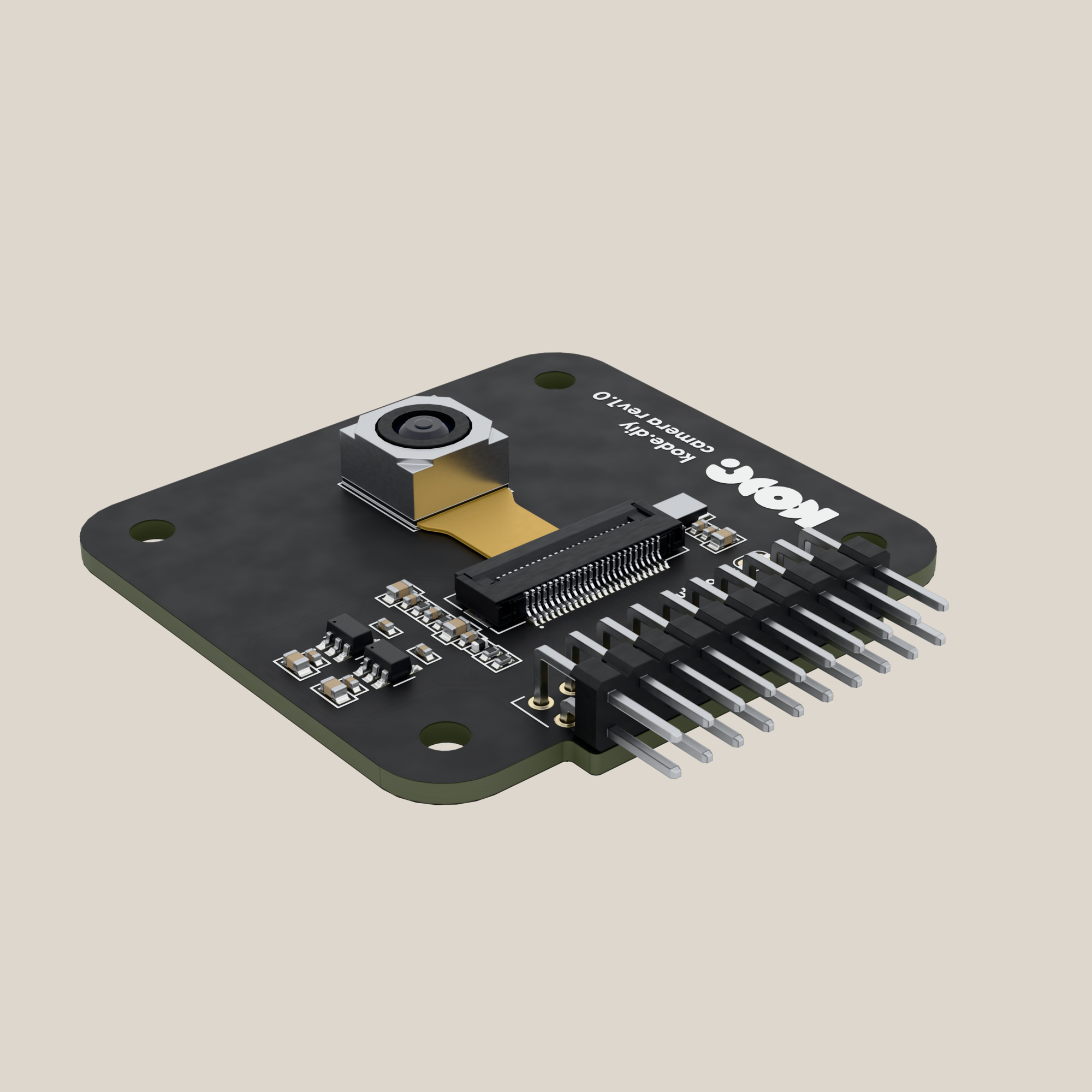
A 5 megapixel camera with autofocus for the Kode Dot, for taking photos, watching video on the screen or handing the image to an AI.
What it is
The Camera module gives the Kode Dot eyes: a 5 megapixel camera with autofocus. It takes photos, shows on the screen what is in front of it, or hands the image to an AI that recognises what it sees, a face or an object. It plugs into the Kode Dot's expansion header.
How it is connected
The module plugs straight into the expansion header and stands upright above the Kode Dot. It goes in two ways and both work. With the lens on the screen side, the camera looks at you. Turned round, it looks away. Each way puts the I2C and the video on different GPIOs.
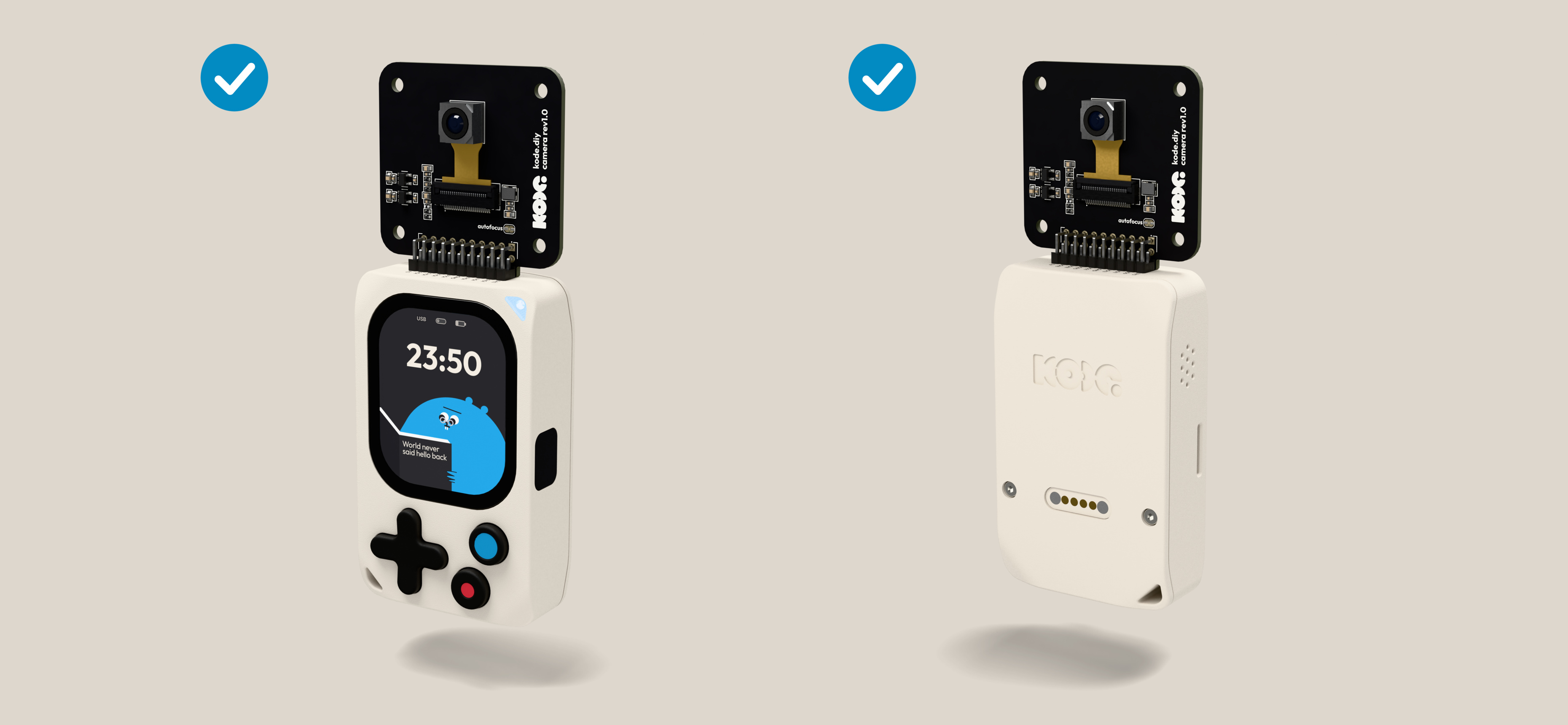
- Push the module's pins into the expansion header, with the lens the way you want it to look: towards you, on the screen side, or away.
- Flash your program with the pins from the matching column of the table below, for example the one at the end of this page.
The 14 GPIOs, for each way of plugging the module in. D2 to D9 are the sensor's data lines, your bits 0 to 7. Everything is an input of the P4 except PWDN, an output, and the I2C pair:
| GPIO | Lens towards you | Lens looking away |
|---|---|---|
GPIO8 | SCL | D4 |
GPIO9 | SDA | D3 |
GPIO10 | VSYNC | D5 |
GPIO11 | PWDN | D2 |
GPIO12 | HSYNC | D6 |
GPIO13 | D9 | PCLK |
GPIO14 | D8 | D7 |
GPIO15 | D3 | SDA |
GPIO16 | D4 | SCL |
GPIO17 | D2 | PWDN |
GPIO18 | D5 | VSYNC |
GPIO19 | PCLK | D9 |
GPIO20 | D6 | HSYNC |
GPIO21 | D7 | D8 |
Both columns come from the netlist of the 2026-10-07 issue, which the 2026-10-26 issue keeps. The same turn rule reproduced the map measured on the earlier camera board.
Specifications
The module:
| Thing | Value |
|---|---|
| Part | KDCMR001, revision 1.0, issue of 2026-10-26. It adds a 220 Ω resistor in series with the sensor's clock, for emissions; the rest of the circuit is the 2026-10-07 issue's |
| Mounts on | The Kode Dot's expansion header, straight |
| Connector | J401, 2 × 10, right-angle male, 2.54 mm. Its numbering is mirrored against the expansion header's: pin 1 of J401, 3.3 V, lands on the header's pin 19 |
| Board | 46.7 × 45.6 mm, two layers, 1.6 mm, four 3.2 mm mounting holes |
| Supplies | 3.3 V from the expansion header. The module makes 1.5 V for the sensor's core (U501) and 2.8 V for its analog side (U502). The focus motor takes the 3.3 V straight. Everything starts when the header's 3.3 V comes up |
| I/O supply | The sensor's DOVDD pin goes to 3.3 V, above the 3.0 V the OV5640 datasheet recommends (absolute maximum 4.5 V). TBD: the limit in the FD5640-500W-V11 datasheet |
| 5 V | Not used |
| Consumption | From the 3.3 V only. About 0.1 A streaming at 800 × 600 and 0.34 A worst case, adding the datasheets. TBD: the current measured on a board |
| Validated | Photos and autofocus from a Kode Dot with Kode's camera app, on a module with this pin map, 2026-10-25. Before that, an earlier camera board with another camera and another pin order answered at 0x3C and sent images both ways round, September 2026 (Kode-Dot-Val/1-EVT/demo/camera_viewer). TBD: an image captured with the 2026-10-26 issue, both ways round |
The camera:
| Thing | Value |
|---|---|
| Sensor | OV5640, 5 MP, autofocus, in an FD5640-500W-V11 camera module on a 24-pin 0.5 mm ribbon, J501. The lens is on the component side |
| Image | Espressif's esp_cam_sensor component offers the OV5640 over DVP one size with the module's 24 MHz clock: 800 × 600 at 10 frames per second. RGB565 at that size is the mode Kode's apps run on a Kode Dot. TBD: a larger size |
| Bus | DVP: eight data lines, D2 to D9, plus PCLK, HSYNC and VSYNC. The sensor has ten data lines and the module wires the top eight |
| Control | SCCB, the sensor's I2C, with 2.2 kΩ pull-ups to 3.3 V on the module. The OV5640 answers at 0x3C, and its registers 0x300A and 0x300B hold its identifier, 0x5640 |
| Clock | A 24 MHz oscillator on the module, through a 220 Ω series resistor (R503) since the 2026-10-26 issue, only for the sensor. No pin of the expansion header carries a clock |
| Reset | A 10 kΩ pull-up and a 100 nF capacitor reset the sensor at power-up. It goes to no GPIO. In software, write 0x82 to register 0x3008 |
| Power-down | PWDN, active high, with a 10 kΩ pull-down: the sensor runs unless you drive it high |
| Autofocus | A voice-coil motor, driven by a processor inside the sensor that starts empty. It needs about 4 KB of firmware over I2C after every power-up; Kode's camera app loads it. TBD: where that firmware ships for your own code |
| Autofocus jumper | JP501, marked autofocus, is closed and carries 3.3 V to pin 23 of the ribbon. Open it if you fit another camera module that uses that pin for something else |
| Image orientation | Registers 0x3820 and 0x3821, bits 2 and 1, flip and mirror the image. TBD: the setting that leaves the image upright for each way of plugging the module in |
| AI | ESP-DL, Espressif's neural network library, runs on the ESP32-P4 and ships models that detect faces and people in the image. TBD: an AI example with this camera run on a Kode Dot |
Gotchas
Example code
For the image, the pieces are ESP-IDF's DVP controller, esp_cam_ctlr_dvp, and Espressif's esp_cam_sensor component, which brings the OV5640 driver. The esp32-camera component has no target for the ESP32-P4.
This example asks the sensor who it is, with the module plugged in with the lens towards you. In the log of idf.py monitor you will see sensor id = 0x5640. If it does not answer, the module is turned round: change the I2C pins to the ones in the comment.
/*
 * camera_id.c - 2026-10-14 - from Kode with love
 *
 * Asks the sensor of the Camera module who it is, with the module plugged
 * in with the lens towards you. Opens its I2C on GPIO8 and GPIO9 and reads
 * registers 0x300A and 0x300B of the OV5640. In the monitor you will see
 * "sensor id = 0x5640". The sensor's clock and reset come from the module
 * itself, so nothing else is needed.
 */
#include <stdio.h>
#include "driver/i2c_master.h"

/* Reads one byte from a sensor register; the sensor has 16-bit addresses. */
static uint8_t sensor_read(i2c_master_dev_handle_t sensor, uint16_t reg)
{
    uint8_t address[2] = { reg >> 8, reg & 0xFF };
    uint8_t value = 0;
    i2c_master_transmit_receive(sensor, address, 2, &value, 1, 100);
    return value;
}

/* Opens the camera's I2C and prints the sensor's identifier. */
void app_main(void)
{
    i2c_master_bus_config_t bus_config = {
        .i2c_port = -1,
        .scl_io_num = 8,   /* with the lens looking away: 16 */
        .sda_io_num = 9,   /* with the lens looking away: 15 */
        .clk_source = I2C_CLK_SRC_DEFAULT,
        .glitch_ignore_cnt = 7,
    };
    i2c_device_config_t sensor_config = { .device_address = 0x3C, .scl_speed_hz = 100000 };
    i2c_master_bus_handle_t bus;
    i2c_master_dev_handle_t sensor;
    i2c_new_master_bus(&bus_config, &bus);
    i2c_master_bus_add_device(bus, &sensor_config, &sensor);

    printf("sensor id = 0x%02X%02X\n", sensor_read(sensor, 0x300A), sensor_read(sensor, 0x300B));
}
Compiled on the date in the header with ESP-IDF v6.1. TBD: a run on a module of the 2026-10-26 issue.
In the SDK
kode.h: in a kodeOS app,kode_exp_power(true)switches the header's 3.3 V on,kode_exp_lend()takes the 14 positions the camera occupies under a name and gives you their GPIO numbers, andkode_exp_ctrl()hands you a free I2C controller for the sensor.- TBD: a camera driver in
kode-sdk. Today,esp_cam_ctlr_dvpandesp_cam_sensor. hardware/camera: the schematic, to view and download.