Modules
F*CK
Sub-GHz, 2.4 GHz, Wi-Fi 6 and GNSS radios in one module: a pocket radio lab for the Kode Dot, with the pins for your code.
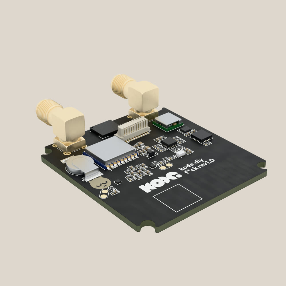
What it is
The F*CK module is a pocket radio lab. With it, the Kode Dot listens to and measures the radios around it and notes where each measurement was taken. It carries four radios:
- A sub-GHz transceiver for 315, 433, 868 and 915 MHz, with its antenna on the board.
- A low-level 2.4 GHz radio, with its antenna on a connector.
- An ESP32-C5 with Wi-Fi 6 on 2.4 and 5 GHz and Bluetooth, with its antenna on the other connector.
- A GNSS receiver, which gives position and time.
To see it work before writing code, install Kode Espectrum. It turns the Kode Dot into a spectrum analyser. TBD: its listing on the marketplace.
The sub-GHz transceiver, a CC1101, is driven by the P4 straight over SPI. The 2.4 GHz radio, an nRF54L15, and the ESP32-C5 run their own firmware, which the P4 loads into them over a UART. Those two do what you program into them.
How it is connected
The module comes in its own case and plugs into the header on the top edge through the interposer, which carries every line straight through. The GPIOs on this page are the header's own.
- Screw an antenna on each connector on top of the case: a dual-band one, 2.4 and 5 GHz, on
J501, and a 2.4 GHz one onJ701. - Seat the module on the top edge of the Kode Dot. The pins enter the header and the case rests against the back.
- Open Kode Espectrum, or your own app for the module. Kode Espectrum shows on the screen what each radio hears.
Five GPIOs go to the CC1101, four to the C5, two to the nRF54L15 and three to the I2C bus with its interrupt, all at 3.3 V. An I2C expander drives the slow lines, such as the resets and the band switch. The GNSS receiver does not reach the header: its UART ends at the C5.
"Pin" is the header's pin, the same as J401's. The direction is the Kode Dot's:
| GPIO | Pin | Signal | Note |
|---|---|---|---|
GPIO8 | 3 | C5 EN | Output. Low holds the C5 in reset. 10 kΩ pull-up |
GPIO9 | 4 | C5 BOOT | Output. Low during a reset starts the C5's bootloader. 10 kΩ pull-up |
GPIO10 | 5 | C5 RX | Output. UART to the C5 |
GPIO11 | 6 | CC1101 MISO | Input. SPI |
GPIO12 | 7 | C5 TX | Input. UART from the C5 |
GPIO13 | 8 | CC1101 SCLK | Output. SPI clock |
GPIO14 | 9 | CC1101 MOSI | Output. SPI |
GPIO15 | 17 | I2C SCL | To the expander and the receiver. 2.2 kΩ pull-up |
GPIO16 | 18 | I2C SDA | To the expander and the receiver. 2.2 kΩ pull-up |
GPIO17 | 15 | CC1101 GDO0 | Input. The transceiver's programmable output |
GPIO18 | 16 | Expander interrupt | Input, active low. 10 kΩ pull-up |
GPIO19 | 13 | CC1101 CS | Output, active low |
GPIO20 | 14 | nRF54L15 RX | Output. UART to the nRF54L15 |
GPIO21 | 12 | nRF54L15 TX | Input. UART from the nRF54L15 |
The schematic and the KiCad sources are in hardware/fck.
Specifications
The module:
| Thing | Value |
|---|---|
| Part | KDFCK001, revision 1.0. Kode's production board is the September 2026 issue with a T filter after the balun, the one that went through radio certification. The repository's current issue, 2026-10-18, carries a new printed antenna and the opposite table for the 315 and 433 MHz legs. TBD: which issue ships |
| Mounts on | The Kode Dot's 20-pin header, through the interposer (KDINT001) inside the case |
| Case | Two parts, base and lid, the same shape as the Mesh module's |
| Board | About 42 × 45 mm, four layers, ENIG, a controlled-impedance stack-up for RF |
| Supply | 3.3 V on pins 2 and 19, ground on 10 and 11. Under 0.8 A, adding the datasheets; the C5 transmitting on 5 GHz takes about 0.43 A. TBD: the current measured on a board |
| 5 V | Not used |
| Expander | TCA6408A (U401) at 0x21, on the module's I2C. P0 and P1: handshake with the C5 · P2: receiver reset · P3: SW0 of the band switch · P4 and P5: handshake with the nRF54L15 · P6: nRF54L15 reset · P7: free. Interrupt on GPIO18. The sub-GHz legs are chosen through it, and that is how it worked in the certification lab on 2026-10-13 |
| Bench firmware | kodediy/fck_module, folder 2-Test_Firmware: a Wi-Fi scan on the C5 with its flasher from the P4, a UART bridge for the nRF54L15 with MCUboot and SMP, CC1101 firmware with a link test between two boards, and RF and GNSS tools. They are examples for testing the board. subghz_cc1101 is for the July boards and subghz_link for revision 1.0. Kode's factory station loads an agent firmware on the C5 and on the nRF54L15, release KDF-SW-FCK-001. TBD: the version that ships and the commands it answers |
| Validated | On boards before the 2026-10-18 issue: the pin map from a Kode Dot, 2026-09-28 and 29. The CC1101 over SPI on two modules, 2026-09-28. A sub-GHz link between two Kode Dots at 2 m on 315, 433.92, 868.35 and 915 MHz, 2026-10-06. NMEA reaching a PC through the C5, 2026-10-01. The C5 scanning Wi-Fi on 2.4 and 5 GHz and the nRF54L15 on its UART, 2026-09-02. TBD: the same on the issue that ships |
The radios:
| Thing | Value |
|---|---|
| Sub-GHz | TI CC1101 over SPI, through a balun and a switched matching network, to an antenna printed on the board (AE601), no connector. The CC1101 covers 300–348, 387–464 and 779–928 MHz. The network has one leg for 315 MHz, one for 433.92 MHz and one for 868 and 915 MHz |
| Band switch | SW0 is the expander's P3. SW1 is the CC1101's GDO2, set with IOCFG2 (0x2F low, 0x6F high). On the certified board: 315 MHz: SW0 low, SW1 high · 433.92 MHz: SW0 high, SW1 low · 868 and 915 MHz: both high · both low isolates the antenna. SW0 floats at power-up: pick a leg before transmitting. The 2026-10-18 issue swaps the 315 and 433.92 MHz legs |
| Sub-GHz antenna | Printed on the board, with the three legs tuned for it. TBD: its matching and its range, measured on the issue that ships |
| 2.4 GHz | Nordic nRF54L15 in a Minewsemi ME54BS61 module, with the radio output straight to the SMA J701. Which protocols it runs is what you load into it; none is documented here |
| nRF54L15 firmware | The first load goes over SWD, on the test points under the board: TP703 SWDIO, TP704 SWCLK, TP702 reset and TP705 ground. After that the P4 updates it over the UART with MCUboot and SMP |
| Wi-Fi 6 and Bluetooth | ESP32-C5-MINI-1U-N4T2, 4 MB of flash and no PSRAM, on the SMA J501. A radio apart from the C5 inside the Kode Dot, which keeps giving it its Wi-Fi |
| Flashing the C5 | EN on GPIO8, BOOT on GPIO9 and its UART on GPIO10 and GPIO12. device/expansion gives GPIO8 to GPIO10 as the lines that flash the Kode Dot's own C5. TBD: whether the two chips can be flashed one at a time with the module on |
| GNSS | Minewsemi ME31GR02, with a Beken BK1661 inside. GPS, BeiDou (B1I and B1C), GLONASS, Galileo, QZSS and SBAS, on L1, per its datasheet. A Quectel YPGS001AA chip antenna on the board. A 0.22 F supercapacitor keeps its memory with the Kode Dot off |
| GNSS data | Its UART and its pulse per second go to the C5: the C5's IO4 receives the receiver's TX and its IO5 sends it commands. To read NMEA from the Kode Dot, run a relay on the C5 that passes that UART to the header's, or read it over I2C. TBD: a fix on a board and its time to first fix |
| GNSS firmware | The receiver needs Minew's dual firmware, which the current issue names in the bill of materials. It prints $FWVER at start-up: V5.26.35.5 is the dual one; V5.25.46.5 is the standard one, which does not answer over I2C and holds SDA high. Minew's NavStarTool updates it through the C5's relay. TBD: a full update over that path, and $FWVER on a board that ships |
| Connectors | J501 is the C5's and J701 the nRF54L15's. Neither is marked on the board. TBD: plain SMA or reverse-polarity SMA, by the connector Kode orders for production |
| Antennas | TBD: which antennas ship with the module and how the case marks each port |
Your country's rules say what you may transmit on each band, at what power and how often. The tables say what the hardware can do.
Gotchas
Example code
To go beyond this read, the RadioLib library has a CC1101 driver. subghz_link, in the module's repository, is Kode's firmware that drives it on revision 1.0.
This example resets the CC1101 and asks it which version it is. In idf.py monitor you will see CC1101 VERSION = 0x14, what two modules answered from a Kode Dot on 2026-09-28. A 0x00 or a 0xFF means the chip does not answer.
/*
 * fck_cc1101.c - 2026-10-14 - from Kode with love
 *
 * Asks the sub-GHz transceiver of the F*CK module, a CC1101, which version
 * it is. Opens its SPI, resets it and reads its VERSION register. In the
 * monitor you will see "CC1101 VERSION = 0x14"; a 0x00 or a 0xFF means the
 * chip does not answer.
 */
#include <stdio.h>
#include "driver/spi_master.h"
#include "freertos/FreeRTOS.h"
#include "freertos/task.h"

#define CC1101_SRES     0x30   /* reset command */
#define CC1101_VERSION  0xF1   /* register 0x31, read as a status register */

/* Sends a one- or two-byte command and returns the last byte answered. */
static uint8_t cc1101_send(spi_device_handle_t cc1101, uint8_t header, int bytes)
{
    spi_transaction_t transfer = { .length = 8 * bytes, .tx_data = { header, 0x00 },
                                   .flags = SPI_TRANS_USE_TXDATA | SPI_TRANS_USE_RXDATA };
    spi_device_transmit(cc1101, &transfer);
    return transfer.rx_data[bytes - 1];
}

/* Opens the module's SPI, resets the CC1101 and prints its version. */
void app_main(void)
{
    spi_bus_config_t bus = { .mosi_io_num = 14, .miso_io_num = 11, .sclk_io_num = 13,
                             .quadwp_io_num = -1, .quadhd_io_num = -1 };
    spi_device_interface_config_t chip = { .clock_speed_hz = 1000000, .spics_io_num = 19,
                                           .queue_size = 1 };
    spi_device_handle_t cc1101;
    spi_bus_initialize(SPI2_HOST, &bus, SPI_DMA_DISABLED);
    spi_bus_add_device(SPI2_HOST, &chip, &cc1101);

    cc1101_send(cc1101, CC1101_SRES, 1);
    vTaskDelay(pdMS_TO_TICKS(10));   /* the chip's oscillator restarts */
    printf("CC1101 VERSION = 0x%02X\n", cc1101_send(cc1101, CC1101_VERSION, 2));
}
Compiled on the date in the header with ESP-IDF v6.1. TBD: a run on a module of the issue that ships.
In the SDK
kode.h: in a kodeOS app,kode_exp_power(true)switches the header's 3.3 V on,kode_exp_lend()takes the module's 14 positions under a name and gives you their GPIO numbers, andkode_exp_ctrl()hands you a free SPI, I2C and two UART controllers for the radios.- TBD: drivers for the four radios in
kode-sdk. hardware/fck: the schematic, to view and download.