Modules
Maker
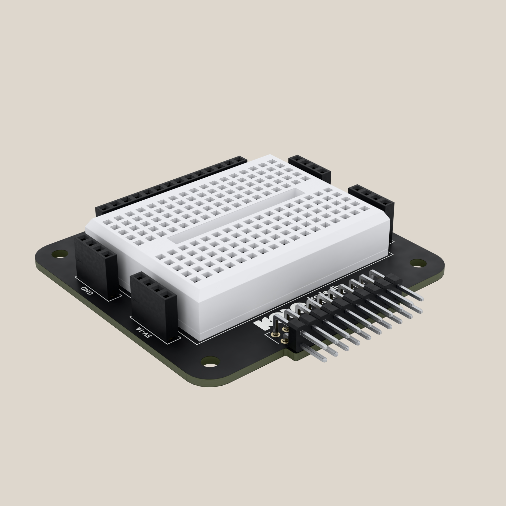
A breadboard and the 14 GPIOs of the Kode Dot in sockets with their name printed, to build your own circuit with no soldering.
What it is
The Maker module is a breadboard for the Kode Dot. It is for trying a circuit of your own, an LED, a button or a sensor, with the Kode Dot as the brain and nothing soldered. It plugs into the Kode Dot's expansion header.
What the module has:
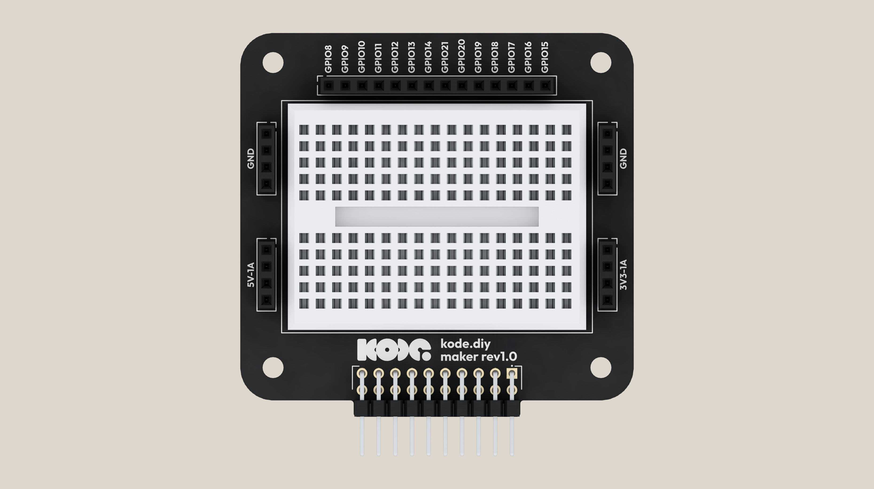
- 14 GPIO sockets, in the top row. Each one goes to a pin of the Kode Dot and has its name printed above it. Six of them,
GPIO16toGPIO21, also read analog voltages. - 4 power strips of four sockets: 5 V and ground on the left, 3.3 V and ground on the right.
- A mini breadboard of 170 tie points in the middle, to build the circuit on.
Your circuit goes on the breadboard, and a jumper wire takes each leg to the socket it needs. The module has no chip: what you wire is what your code sees.
How it is connected
The module plugs straight into the expansion header and stands upright above the Kode Dot. It fits both ways, and only one is right: with the breadboard on the same side as the screen. Turned round, power still arrives, but every GPIO socket lands on another pin and the printed names stop being true.
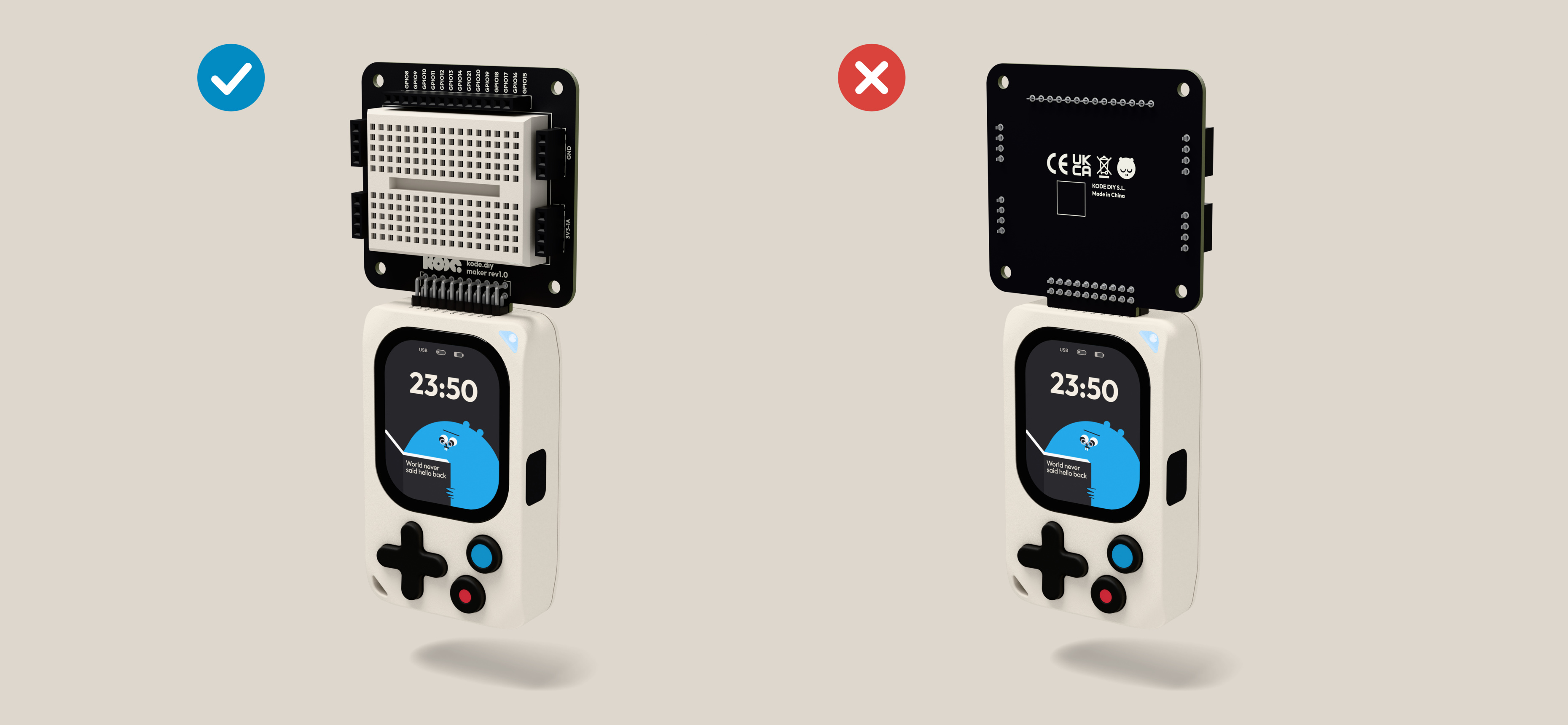
- Push the module's pins into the expansion header, with the breadboard on the screen side.
- Build your circuit on the breadboard and take it with jumper wires to the sockets it needs, by the name printed on each one.
- Flash your program onto the Kode Dot with
idf.py flash, for example the one at the end of this page. Your circuit responds.
The GPIO row is not in numeric order: it runs from GPIO8 to GPIO14 and then down from GPIO21 to GPIO15. Wire by the printed name, which is the one in the table below.
Specifications
| Thing | Value |
|---|---|
| Part | KDMKR001, revision 1.0, issue of 2026-10-26. Same circuit as the 2026-10-07 issue; black solder mask and production part numbers for the connectors |
| Mounts on | The Kode Dot's expansion header, straight, with the breadboard on the screen side |
| GPIO row | J502, 14 female 2.54 mm sockets. With the module on and the breadboard facing you, left to right: GPIO8, GPIO9, GPIO10, GPIO11, GPIO12, GPIO13, GPIO14, GPIO21, GPIO20, GPIO19, GPIO18, GPIO17, GPIO16, GPIO15 |
| Turned round | Power lands in the same place, because the 3.3 V, 5 V and ground pins of the module's connector, J401, come in symmetric pairs (1 and 20, 2 and 19, 9 and 12). The GPIOs do not: the printed row becomes GPIO16, 15, 18, 17, 20, 19, 21, 14, 12, 13, 10, 11, 8, 9, the signal of header position p lands on position 15 − p, a rule measured on this module and on the Camera |
| Analog | GPIO16 to GPIO21 read analog on ADC1, as on the expansion header |
| Power strips | Four of 4 female sockets: 5 V (J503) and ground on the left, 3.3 V (J504) and ground on the right. The two ground strips are J505 and J506 |
| Breadboard | SYB-170, 170 tie points, 45.5 × 34.5 mm, glued to the board |
| Active parts | None. No pull-ups on any line: an I2C sensor needs a resistor of about 4.7 kΩ from each line to 3.3 V, or a sensor board that brings its own |
| 5 V budget | On USB, the expansion header's: a 2 A resettable fuse, 1.5 A at 60 °C (device/expansion). On battery, off until your firmware asks for the boost, which gives 0.5 A (device/power) |
| Strip markings | The 2026-10-07 issue and later print 5V-1A and 3V3-1A; the first prototypes, 2 A. TBD: the current Kode guarantees |
| Silkscreen | The 2026-10-07 issue and later print the GPIOs in this table's order. The first prototypes print names from an earlier Kode Dot (GPIO1, TXD, GPIO39) and also say rev1.0: with one of those, follow this table. TBD: whether their copper follows the same order |
Gotchas
Example code
Lights an LED while you hold a button. Fit the LED with a 330 Ω resistor from the GPIO12 socket to ground, long leg towards GPIO12, and the button from the GPIO13 socket to ground. Press, and the LED lights; release, and it goes off.
/*
 * maker_button_led.c - 2026-10-14 - from Kode with love
 *
 * Lights an LED while you hold a button, both on the breadboard of the
 * Maker module. The LED goes with its resistor from the GPIO12 socket to
 * ground, and the button from the GPIO13 socket to ground. The button needs
 * no resistor: the pin's internal pull-up holds it high until you press.
 */
#include "driver/gpio.h"
#include "freertos/FreeRTOS.h"
#include "freertos/task.h"

#define LED_PIN     GPIO_NUM_12
#define BUTTON_PIN  GPIO_NUM_13

/* Makes the LED an output and the button an input with a pull-up. */
static void pins_setup(void)
{
    gpio_reset_pin(LED_PIN);
    gpio_set_direction(LED_PIN, GPIO_MODE_OUTPUT);

    gpio_reset_pin(BUTTON_PIN);
    gpio_set_direction(BUTTON_PIN, GPIO_MODE_INPUT);
    gpio_set_pull_mode(BUTTON_PIN, GPIO_PULLUP_ONLY);
}

/* Copies the button to the LED a hundred times a second: pressed reads 0 and lights it. */
void app_main(void)
{
    pins_setup();

    while (1) {
        int pressed = gpio_get_level(BUTTON_PIN) == 0;
        gpio_set_level(LED_PIN, pressed);
        vTaskDelay(pdMS_TO_TICKS(10));
    }
}
Compiled on the date in the header with ESP-IDF v6.1. TBD: a run on a module. These are the ordinary GPIO calls of ESP-IDF, as in device/expansion, because the module puts nothing in between.
In the SDK
kode.h: in a kodeOS app,kode_exp_input(),kode_exp_output(),kode_exp_adc()andkode_exp_pwm()drive a header position straight, by position number, andkode_exp_lend()takes the positions your circuit uses under a name and gives you their GPIO numbers for ESP-IDF.hardware/maker: the schematic, to view and download.