Modules
Mesh
A LoRa radio and a GNSS receiver for the Kode Dot: messages that travel far and your position with no network, with the pins for your code.
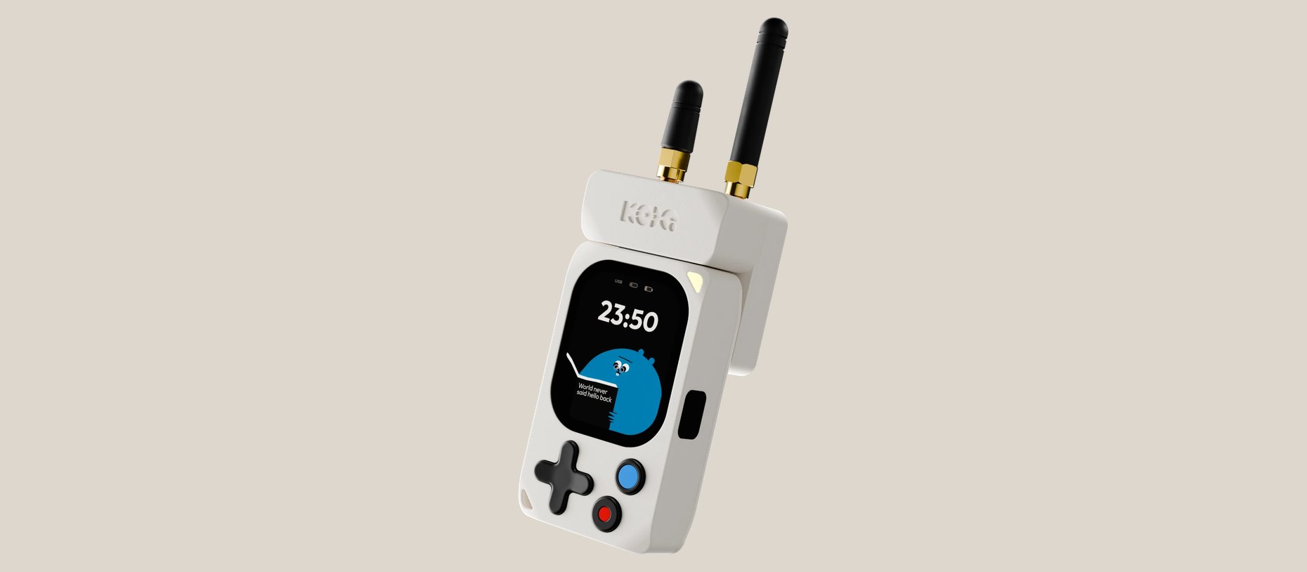
What it is
The Mesh module lets the Kode Dot send messages to radios far away and know where it is. It needs no Wi-Fi and no phone, so it works where neither reaches, out in the hills or during a blackout. It carries two parts:
- A LoRa radio, which sends short messages a long way on very little power, to other Kode Dots with the module and to LoRa radios with the same settings. It has a sub-GHz port and a 2.4 GHz port.
- A GNSS receiver, which listens to GPS and the other satellite systems and gives position and time.
To see it work before writing code, install MeshKode. It turns the Kode Dot into a Meshtastic node, with chat, a map and the position of every node it hears. TBD: its listing on the marketplace. The radio is a NiceRF LoRa2021, with a Semtech LR2021 inside, and the receiver a Minewsemi ME31GR02.
How it is connected
The module comes in its own case and plugs into the header on the top edge. Inside, its board sits on the interposer, a passive adapter that carries every line straight through, so the GPIOs on this page are the header's own.
- Screw an antenna on each connector on top of the case. Both stand upright.
- Seat the module on the top edge of the Kode Dot. The pins enter the header and the case rests against the back.
- Open MeshKode, or your own app for the module. MeshKode shows the nodes it hears and, outdoors, your position.
The radio uses eight GPIOs: the SPI, a busy line, a reset and two DIOs. The receiver uses six: a UART at 115200 baud, a reset, a pulse per second and an I2C pair. All at 3.3 V. "Pin" is the header's pin, the same as J401's on the board, and the direction is the Kode Dot's:
| GPIO | Pin | Signal | Note |
|---|---|---|---|
GPIO8 | 3 | GNSS reset | Output, active low. No pull-up on the module: drive it high |
GPIO9 | 4 | GNSS TX | Input. The NMEA arrives here, at 115200 baud |
GPIO10 | 5 | GNSS 1PPS | Input. One pulse per second once the receiver has a fix |
GPIO11 | 6 | GNSS RX | Output. Commands to the receiver |
GPIO12 | 7 | LoRa reset | Output, active low. 10 kΩ pull-up |
GPIO13 | 8 | LoRa DIO9 | Input. The radio's interrupt |
GPIO14 | 9 | LoRa DIO8 | Input. Free |
GPIO15 | 17 | I2C SCL | To the receiver. 2.2 kΩ pull-up |
GPIO16 | 18 | I2C SDA | To the receiver. 2.2 kΩ pull-up |
GPIO17 | 15 | LoRa MOSI | Output. SPI, to the radio |
GPIO18 | 16 | LoRa BUSY | Input. High while the radio works: wait for it to drop before every command |
GPIO19 | 13 | LoRa MISO | Input. SPI, from the radio |
GPIO20 | 14 | LoRa CS | Output, active low. 10 kΩ pull-up |
GPIO21 | 12 | LoRa SCK | Output. SPI clock |
The labels the case prints beside the header, screen up and top edge towards you:
| Row, left to right | Labels on the case |
|---|---|
| Screen side, pins 19 to 1 | 3V3 IO15 IO17 IO19 GND IO14 IO12 IO10 IO8 5V |
| Back side, pins 20 to 2 | 5V IO16 IO18 IO20 IO21 GND IO13 IO11 IO9 3V3 |
With the Kode Dot upright and the edge seen from above, left and right swap. The schematic and the KiCad sources are in hardware/mesh.
Specifications
The module:
| Thing | Value |
|---|---|
| Part | KDMSH001, revision 1.0, issue of 2026-10-26. Same circuit as the 2026-10-07 issue; black solder mask, and the receiver's firmware named in the bill of materials |
| Mounts on | The Kode Dot's 20-pin header, through the interposer (KDINT001) inside the case |
| Case | Two parts, base and lid, the same shape as the F*CK module's |
| Board | 41.9 × 44.7 mm, four layers |
| Supply | 3.3 V on pins 2 and 19, ground on 10 and 11. Under 0.25 A, adding the datasheets. The radio alone draws 142 mA transmitting at +22 dBm on 868 MHz, measured by NiceRF. TBD: the current measured on a board |
| 5 V | Not used |
| Validated | On boards of the 2026-09-14 issue: the GNSS over the UART, the pulse per second, the I2C and the radio answering over SPI, between 2026-09-29 and 2026-10-02. Two Kode Dots running MeshKode exchange text and voice. TBD: the same on the 2026-10-26 issue |
The radio:
| Thing | Value |
|---|---|
| Radio | NiceRF LoRa2021, with a Semtech LR2021 inside |
| Sub-GHz | 863–928 MHz on J501, which covers the 868 MHz and 915 MHz bands |
| 2.4 GHz | On J502 |
| Power | Up to +22 dBm on J501 and +12 dBm on J502, the limits of the LR2021 driver in RadioLib 7.7.1. On 868 MHz, with the amplifier settings Kode's certified firmware uses, 13.1–14.1 dBm measured. TBD: the power measured on J502 |
| RF path | One port per band, no RF switch. The radio's DIO7 is not connected |
| Regulator | LDO mode. The module does not bring out the DC-DC pins |
| Meshtastic | MeshKode is a Meshtastic build with a driver for the LR2021. A stock Meshtastic image does not drive this radio |
| Connectors | TBD: plain SMA or reverse-polarity SMA, by the connector Kode orders for production |
| Antennas | TBD: which antennas ship with the module and how the case marks each port |
Your country's rules say what you may transmit on each band, at what power and how often. The table says what the hardware can do.
The receiver:
| Thing | Value |
|---|---|
| Receiver | Minewsemi ME31GR02, with a Beken BK1661 inside |
| Systems | GPS, BeiDou (B1I and B1C), GLONASS, Galileo, QZSS and SBAS, on L1, per the part's datasheet |
| Output | NMEA over a UART at 115200 baud, and a pulse per second on GPIO10 |
| Antenna | A Quectel YPGS001AA chip antenna on the board, no connector for an external one |
| Backup | A 0.22 F supercapacitor keeps the receiver's memory while the Kode Dot is off. TBD: for how long |
| I2C | GPIO15 for SCL and GPIO16 for SDA. The receiver answers at 0x54 only with Minew's dual firmware, which prints $FWVER V5.26.35.5 at start-up. The 2026-10-26 issue names that firmware in the bill of materials; the boards reviewed on 2026-09-28 carried the standard one, V5.25.46.5. TBD: $FWVER on a board of this issue |
| Start-up | TBD: the time to first fix, cold and warm, measured outdoors |
| While transmitting | TBD: whether the receiver keeps its fix while the radio transmits |
Gotchas
Example code
For the LoRa radio, the library is RadioLib, the one Meshtastic uses, with its LR2021 driver and the pins from the table. For the receiver's sentences any NMEA library works, and ESP-IDF ships an example, peripherals/uart/nmea0183_parser.
This example takes the receiver out of reset and copies everything it sends to the log. In idf.py monitor you will see NMEA sentences, lines starting with $, once a second. Indoors they come with empty fields until the receiver sees satellites.
/*
 * mesh_gnss.c - 2026-10-14 - from Kode with love
 *
 * Copies to the log what the GNSS receiver of the Mesh module says. Takes
 * the receiver out of reset with GPIO8 and opens its UART at 115200 baud on
 * GPIO9 and GPIO11. In the monitor you will see NMEA sentences, lines that
 * start with $, once a second; indoors they come with empty fields.
 */
#include <stdio.h>
#include "driver/gpio.h"
#include "driver/uart.h"

#define GNSS_RESET        GPIO_NUM_8    /* active low, no pull-up on the module */
#define GNSS_DATA_IN      GPIO_NUM_9    /* the NMEA arrives here */
#define GNSS_COMMAND_OUT  GPIO_NUM_11   /* commands to the receiver */

/* Takes the receiver out of reset and logs every byte it sends. */
void app_main(void)
{
    gpio_set_direction(GNSS_RESET, GPIO_MODE_OUTPUT);
    gpio_set_level(GNSS_RESET, 1);

    uart_config_t uart = {
        .baud_rate = 115200,
        .data_bits = UART_DATA_8_BITS,
        .parity = UART_PARITY_DISABLE,
        .stop_bits = UART_STOP_BITS_1,
        .source_clk = UART_SCLK_DEFAULT,
    };
    uart_driver_install(UART_NUM_1, 2048, 0, 0, NULL, 0);
    uart_param_config(UART_NUM_1, &uart);
    uart_set_pin(UART_NUM_1, GNSS_COMMAND_OUT, GNSS_DATA_IN, UART_PIN_NO_CHANGE, UART_PIN_NO_CHANGE);

    uint8_t text[256];
    while (1) {
        int length = uart_read_bytes(UART_NUM_1, text, sizeof(text), portMAX_DELAY);
        fwrite(text, 1, length, stdout);   /* every sentence brings its own line end */
    }
}
Compiled on the date in the header with ESP-IDF v6.1. TBD: a run on a module.
In the SDK
kode.h: in a kodeOS app,kode_exp_power(true)switches the header's 3.3 V on,kode_exp_lend()takes the module's 14 positions under a name and gives you their GPIO numbers, andkode_exp_ctrl()hands you a free SPI, UART and I2C controller for the radio and the receiver.- TBD: a LoRa2021 driver in
kode-sdk. Today RadioLib drives the LR2021. - TBD: an NMEA parser in
kode-sdk.