Módulo: Pro

Características

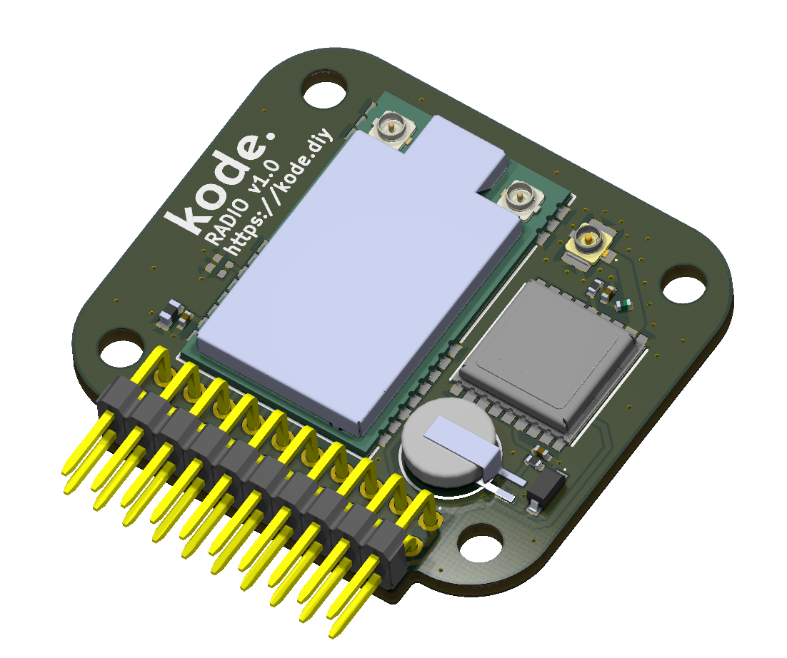
Con este módulo puedes desde comunicarte con LoRa hasta ubicarte con GNSS. Integra un módulo LoRa E80-900M2213S (LR1121) de Ebyte y un módulo GNSS MAX-M10S de U-Blox. Estamos trabajando en la integración con Meshtastic.

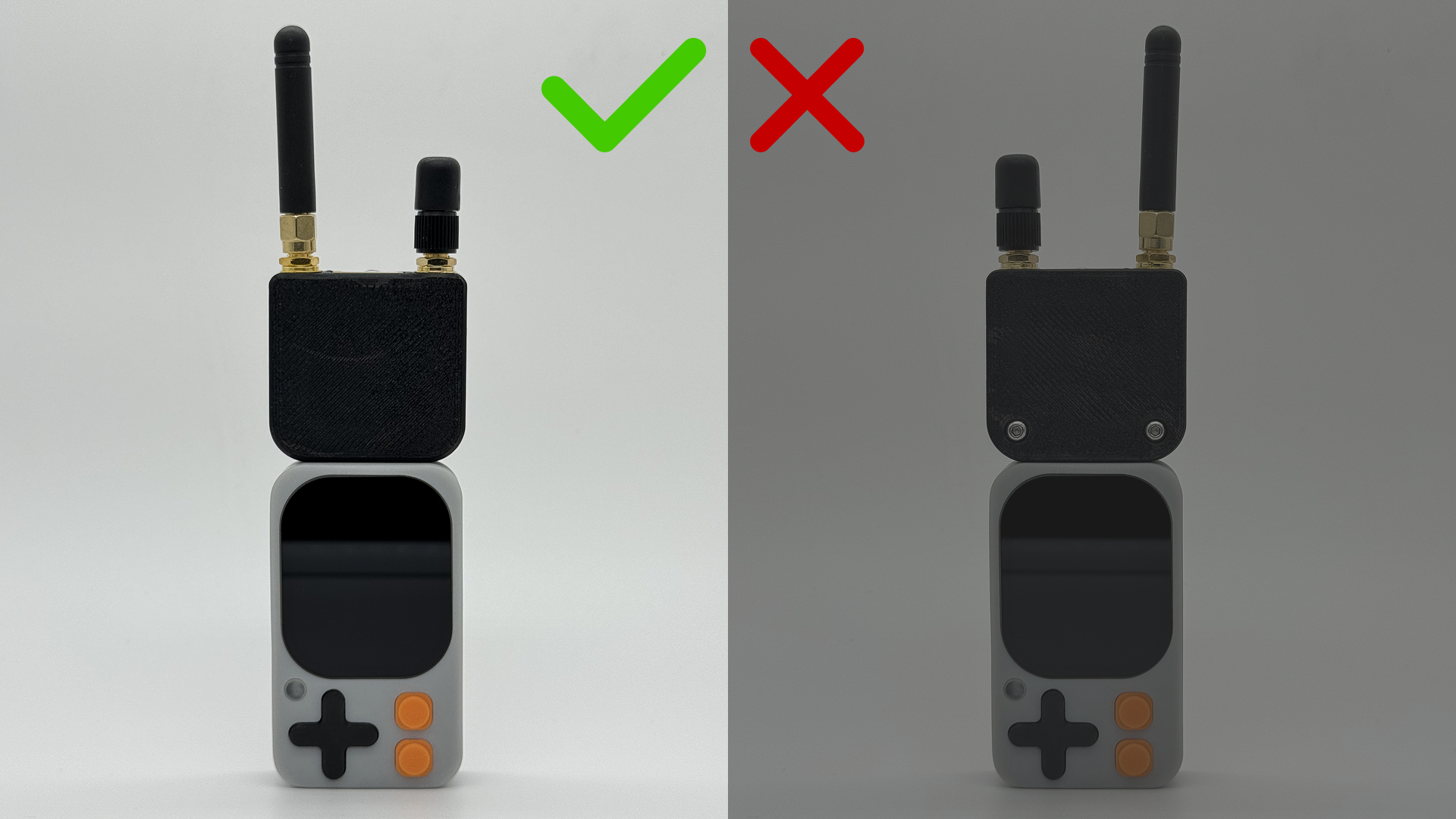
Conexión con el kode dot

Esquema de conexión

Módulo LoRa

El módulo Ebyte E80-900M2213S está conectado al ESP32-S3 de la siguiente manera:
E80-900M2213SESP32-S3
MISOGPIO41
MOSIGPIO40
SCKGPIO39
NSS (CS)GPIO3
BUSYGPIO13
LR_NRESETGPIO2
DIO9GPIO12
DIO8GPIO1
DIO7GPIO11

Módulo GNSS

El módulo GNSS MAX-M10S está conectado al ESP32-S3 de la siguiente manera:
MAX-M10SESP32-S3
TXDGPIO44
RXDGPIO43
SCLGPIO47
SDAGPIO48

Ejemplos de código

Comunicación con LoRa

Para usar el módulo LoRa, recomendamos usar la librería RadioLib Este código es un ejemplo de cómo usar el módulo LoRa para escanear las bandas de 868 MHz y 2.4 GHz.
lora_test.ino
/**
 * Escáner de canales LR1121 (solo RX, sin TX).
 * Barre las bandas de 868 MHz y 2.4 GHz cambiando BW y SF dinámicamente.
 * Mide el RSSI (ruido de canal) y muestra los resultados en formato CSV.
 */
/* ───────── KODE | docs.kode.diy ───────── */

#include <Arduino.h>
#include <RadioLib.h>

/* Configuración de pines (según tu diseño) */
#define NSS_PIN    3    /* Chip Select */
#define DIO1_PIN   12   /* IRQ */
#define NRST_PIN   2    /* Reset */
#define BUSY_PIN   13   /* Busy */
#define MISO_PIN   41
#define MOSI_PIN   40
#define SCK_PIN    39

/* Mapeo del RF Switch para E80-900M2213S */
static const uint32_t rfswitch_dio_pins[] = {
  RADIOLIB_LR11X0_DIO5, RADIOLIB_LR11X0_DIO6,
  RADIOLIB_NC, RADIOLIB_NC, RADIOLIB_NC
};
static const Module::RfSwitchMode_t rfswitch_table[] = {
  { LR11x0::MODE_STBY,  { LOW,  LOW  } },
  { LR11x0::MODE_RX,    { LOW,  LOW  } },  /* RX */
  { LR11x0::MODE_TX,    { LOW,  HIGH } },  /* TX Sub-1GHz LP */
  { LR11x0::MODE_TX_HP, { HIGH, LOW  } },  /* TX Sub-1GHz HP */
  { LR11x0::MODE_TX_HF, { HIGH, HIGH } },  /* TX 2.4GHz */
  { LR11x0::MODE_GNSS,  { LOW,  LOW  } },
  { LR11x0::MODE_WIFI,  { LOW,  LOW  } },
  END_OF_MODE_TABLE,
};

/* Instancias */
SPIClass spi(HSPI);
LR1121 radio = new Module(NSS_PIN, DIO1_PIN, NRST_PIN, BUSY_PIN, spi);

/* Configuración de barrido de frecuencias */
const float FREQS_868[] = { 863.0, 866.0, 868.0, 869.5 };
const float FREQS_24[]  = { 2403.5, 2425.0, 2450.0, 2479.5 };
const size_t N_868 = sizeof(FREQS_868) / sizeof(FREQS_868[0]);
const size_t N_24  = sizeof(FREQS_24)  / sizeof(FREQS_24[0]);

/* Parámetros dinámicos */
const float  BWS_KHZ[] = { 125.0, 203.125 };
const int    SFS[]     = { 7, 9, 12 };
const int    CR        = 5;
const int    PWR_DBM   = 10;
const uint8_t PREAMBLE = 8;
const float  TCXO_V    = 1.8;

/* Tiempo de escucha por punto de medida */
const uint16_t DWELL_MS = 200;

/* Funciones auxiliares */
/* Reset físico del LR1121 */
static void hardResetModule() {
  pinMode(NRST_PIN, OUTPUT);
  digitalWrite(NRST_PIN, LOW);
  delay(50);
  digitalWrite(NRST_PIN, HIGH);
  delay(50);
}

/* Configura el LR1121 con los parámetros indicados */
static bool configRadio(float freqMHz, float bwkHz, int sf) {
  int st = radio.begin(freqMHz, bwkHz, sf, CR, 0x12 /*sync*/, PWR_DBM, PREAMBLE, TCXO_V);
  if (st != RADIOLIB_ERR_NONE) {
    Serial.print("Fallo de configuración  f="); Serial.print(freqMHz, 3);
    Serial.print(" MHz  BW="); Serial.print(bwkHz, 3);
    Serial.print(" kHz  SF="); Serial.print(sf);
    Serial.print("  código="); Serial.println(st);
    return false;
  }
  return true;
}

/* Mide una vez el RSSI con los parámetros indicados y muestra línea CSV */
static void measureOnce(float freqMHz, float bwkHz, int sf, const char* bandTag) {
  if (!configRadio(freqMHz, bwkHz, sf)) return;

  /* Iniciar recepción */
  int st = radio.startReceive();
  if (st != RADIOLIB_ERR_NONE) {
    Serial.print("Fallo al iniciar RX, código="); Serial.println(st);
    return;
  }

  delay(DWELL_MS);
  float rssi = radio.getRSSI();

  /* Salida en formato CSV: BANDA,FREQ_MHz,BW_kHz,SF,RSSI_dBm */
  Serial.print(bandTag); Serial.print(",");
  Serial.print(freqMHz, 3); Serial.print(",");
  Serial.print(bwkHz, 3); Serial.print(",");
  Serial.print(sf); Serial.print(",");
  Serial.println(rssi, 1);

  radio.standby();
}

/* Escanea toda una banda de frecuencias variando BW y SF */
static void scanBand(const float* freqs, size_t nFreq, const char* bandTag) {
  Serial.println();
  Serial.println("BANDA,FREQ_MHz,BW_kHz,SF,RSSI_dBm");
  for (size_t i = 0; i < nFreq; i++) {
    for (size_t b = 0; b < sizeof(BWS_KHZ)/sizeof(BWS_KHZ[0]); b++) {
      for (size_t s = 0; s < sizeof(SFS)/sizeof(SFS[0]); s++) {
        measureOnce(freqs[i], BWS_KHZ[b], SFS[s], bandTag);
      }
    }
  }
}

/* Setup */
void setup() {
  Serial.begin(115200);
  while (!Serial) { delay(10); }
  Serial.println("\n=== Escáner de canales LR1121 (solo RSSI) ===");
  Serial.println("RSSI = ruido de canal (más cerca de 0 => más ruido)");

  pinMode(BUSY_PIN, INPUT);

  Serial.println("Reseteando módulo...");
  hardResetModule();

  Serial.println("Inicializando SPI...");
  spi.begin(SCK_PIN, MISO_PIN, MOSI_PIN, NSS_PIN);

  radio.setRfSwitchTable(rfswitch_dio_pins, rfswitch_table);

  Serial.println("\n--- Escaneo: 868 MHz ---");
  scanBand(FREQS_868, N_868, "868MHz");

  Serial.println("\n--- Escaneo: 2.4 GHz ---");
  scanBand(FREQS_24, N_24, "2400MHz");

  Serial.println("\nFin del escaneo. Reinicia para repetir.");
}

/* Loop */
void loop() {
  delay(1000);
}
Ubicación con GNSS

Para usar el módulo GNSS, recomendamos usar la librería SparkFun u-blox GNSS

Uso por I2C

Este código es un ejemplo de cómo usar el módulo GNSS por I2C.
gnss_test_I2C.ino
/**
 * Ejemplo: Lectura de datos GNSS (GPS) desde un Módulo de Radio Kode vía I2C.
 * Obtiene latitud, longitud y altitud del módulo u-blox.
 * Utiliza el mensaje PVT (Posición, Velocidad, Tiempo) para la lectura de datos.
 */
/* ───────── KODE | docs.kode.diy ───────── */

#include <SparkFun_u-blox_GNSS_v3.h>
#include <Wire.h>

/* Objeto del módulo GNSS */
SFE_UBLOX_GNSS myGNSS;

void setup()
{
  Serial.begin(115200);
  delay(1000); 
  Serial.println("Ejemplo de Módulo de Radio Kode");

  /* ─── Inicializar I2C con SDA = GPIO48, SCL = GPIO47 ─── */
  Wire.begin(48, 47);

  /* Habilitar mensajes de depuración GNSS por Serial (opcional) */
  myGNSS.enableDebugging(); // Comenta esta línea para desactivar mensajes de depuración

  /* Intentar conectar con el módulo GNSS u-blox hasta que tenga éxito */
  while (myGNSS.begin() == false)
  {
    Serial.println(F("u-blox GNSS no detectado. Reintentando..."));
    delay(1000);
  }

  /* Configurar salida I2C en protocolo UBX únicamente (desactiva mensajes NMEA) */
  myGNSS.setI2COutput(COM_TYPE_UBX);
}

void loop()
{
  /* Si hay datos PVT disponibles, leerlos y mostrarlos */
  if (myGNSS.getPVT() == true)
  {
    /* Obtener e imprimir latitud */
    int32_t latitude = myGNSS.getLatitude();
    Serial.print(F("Lat: "));
    Serial.print(latitude);

    /* Obtener e imprimir longitud */
    int32_t longitude = myGNSS.getLongitude();
    Serial.print(F(" Long: "));
    Serial.print(longitude);
    Serial.print(F(" (grados * 10^-7)"));

    /* Obtener e imprimir altitud (MSL) */
    int32_t altitude = myGNSS.getAltitudeMSL();
    Serial.print(F(" Alt: "));
    Serial.print(altitude);
    Serial.print(F(" (mm)"));

    Serial.println();
  }
}

Uso por UART

Este código es un ejemplo de cómo usar el módulo GNSS por UART.
gnss_test_UART.ino
#include <SparkFun_u-blox_GNSS_v3.h>

/* Objeto GNSS para comunicación vía puerto serie */
SFE_UBLOX_GNSS_SERIAL myGNSS;

/* ─── Mapeo de pines para UART GNSS ───
 * GNSS_RX_PIN → pin del MCU que recibe datos desde TX del GNSS
 * GNSS_TX_PIN → pin del MCU que envía datos hacia RX del GNSS
 */
static const int GNSS_RX_PIN = 44; // MCU recibe por GPIO44
static const int GNSS_TX_PIN = 43; // MCU transmite por GPIO43

/* Instancia de puerto serie hardware (UART1) */
HardwareSerial GNSSSerial(1);

void setup()
{
  Serial.begin(115200);
  delay(1000);
  Serial.println("u-blox GNSS vía UART1 (GPIO44/43)");

  /* ─── Inicializar UART1 en los pines indicados ───
   * Velocidad: 38400 baudios
   * Formato: 8 bits, sin paridad, 1 bit de stop (SERIAL_8N1)
   */
  GNSSSerial.begin(38400, SERIAL_8N1, GNSS_RX_PIN, GNSS_TX_PIN);

  /* Activar mensajes de depuración en el puerto serie principal (opcional) */
  myGNSS.enableDebugging(Serial);

  /* Configurar salida de datos por UART1 → Solo protocolo UBX, sin NMEA */
  myGNSS.setUART1Output(COM_TYPE_UBX);

  /* Intentar conectar con el módulo GNSS hasta que responda */
  while (!myGNSS.begin(GNSSSerial)) {
    Serial.println(F("u-blox GNSS no detectado. Reintentando..."));
    delay(1000);
  }
}

void loop()
{
  /* Si hay datos PVT (Posición, Velocidad, Tiempo) disponibles, mostrarlos */
  if (myGNSS.getPVT()) {
    int32_t lat = myGNSS.getLatitude();      // Latitud en grados * 10^-7
    int32_t lon = myGNSS.getLongitude();     // Longitud en grados * 10^-7
    int32_t alt = myGNSS.getAltitudeMSL();   // Altitud MSL en milímetros

    Serial.print(F("Lat: ")); Serial.print(lat);
    Serial.print(F(" Long: ")); Serial.print(lon);
    Serial.print(F(" (deg*1e-7) Alt: ")); Serial.print(alt);
    Serial.println(F(" (mm)"));
  }
}

Descarga de ejemplos

Puedes probar los códigos de ejemplo mediante el IDE de Arduino o el IDE de ESP-IDF o descargar los códigos en nuestro drive: Ejemplos de código del módulo Inventor