Hardware
Main board
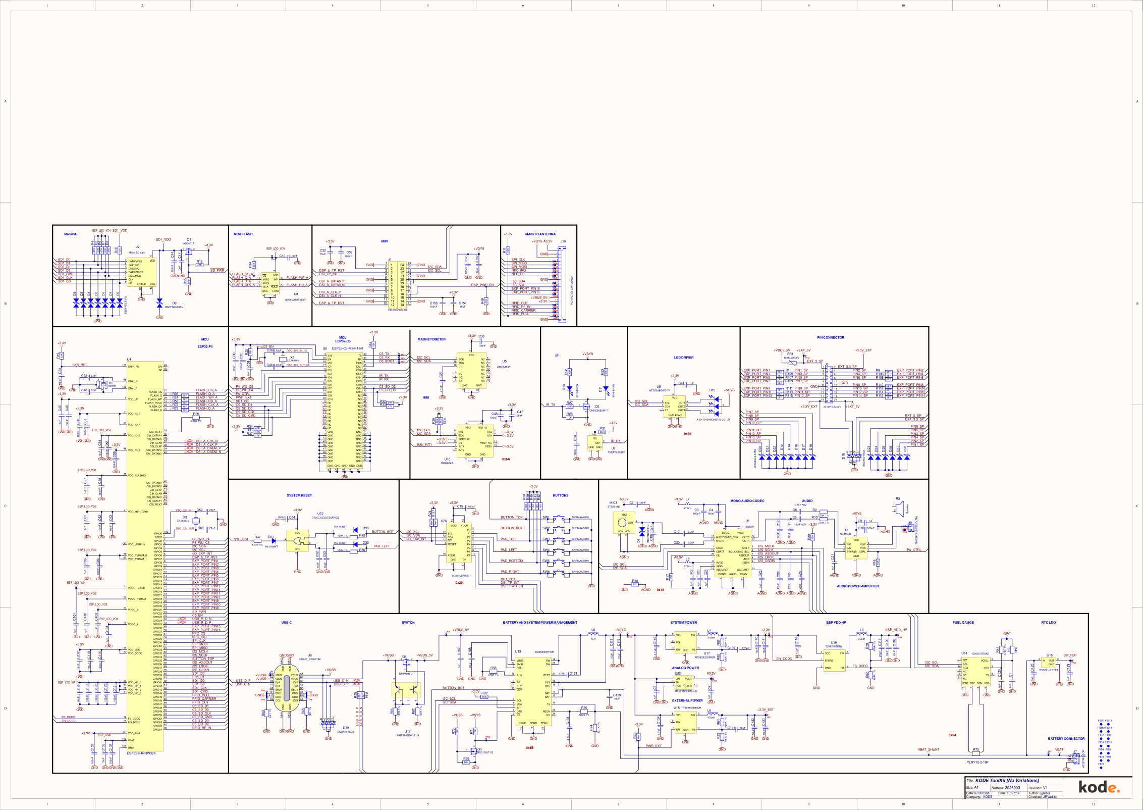
The Kode Dot's main board schematic, KODE ToolKit V1: the P4, the C5, memory, power, audio, motion, the display and header connectors, on one sheet.
What it is
The main board is the Kode Dot: the ESP32-P4 and its flash, the ESP32-C5
radio module, the display and touch connector, the motion sensors, the audio
codec and amplifier, the LED driver, the infrared pair, the buttons through
their expander, the charger, the fuel gauge and the regulators, the USB-C
port, the microSD slot and the 20-pin expansion header. The antenna board
hangs off it over a 20-way flex, and has its own page at
hardware/antenna-board.
The design is KODE ToolKit, number 2026003, revision V1, the production board, dated 2026-09-07. It was drawn in Altium by Versa Design for Kode. One A1 sheet holds every block, each in its own frame with its name at the top.
Schematic
Scroll to zoom and drag to pan. Every block is labelled: find the part you are after by its frame title.
The sheet as a plain image: main board.
Files
- main-board-schematic.pdf: the schematic, one A1 sheet.
- main-board.svg: the same sheet as SVG.
TBD: the KiCad sources, the manufacturing package (Gerbers, drills, BOM, positions) and the licence.