Hardware
Antenna board
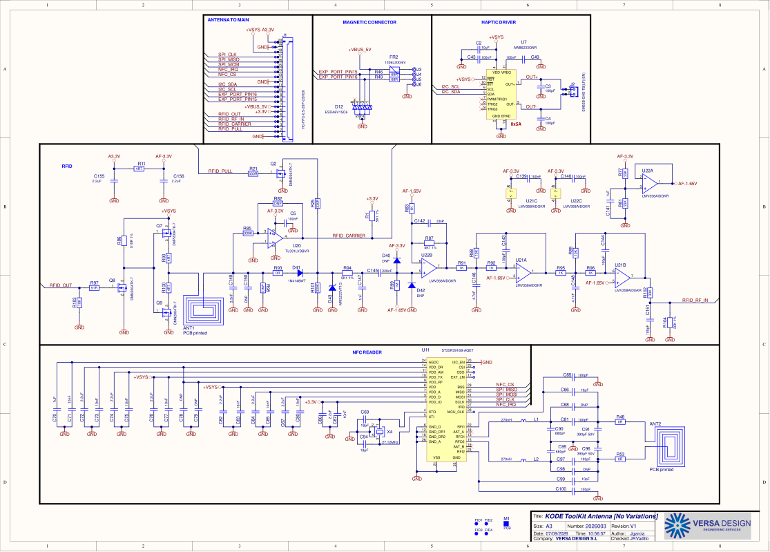
The Kode Dot's antenna board schematic, KODE ToolKit Antenna V1: the NFC reader, the 125 kHz RFID front end, the haptic driver and the magnetic connector.
What it is
The antenna board sits behind the back of the case and carries what needs to be near the surface: the ST25R3916B NFC reader with its 13.56 MHz loop, the 125 kHz RFID front end with its own loop and the analogue chain that demodulates a card, the haptic driver, and the magnetic pogo connector with its fuse. It reaches the main board over a 20-way flex, which carries the SPI, the I2C, the RFID lines and power.
The design is KODE ToolKit Antenna, number 2026003, revision V1, dated 2026-09-07, drawn in Altium by Versa Design for Kode. One A3 sheet.
Schematic
Scroll to zoom and drag to pan. The four frames are the flex connector, the magnetic connector and haptic driver, the RFID front end, and the NFC reader.
The sheet as a plain image: antenna board.
Files
- antenna-board-schematic.pdf: the schematic, one A3 sheet.
- antenna-board.svg: the same sheet as SVG.
TBD: the KiCad sources, the manufacturing package and the licence.