> ## Documentation Index
> Fetch the complete documentation index at: https://docs.kode.diy/llms.txt
> Use this file to discover all available pages before exploring further.
# Radio
> Comunicate con LoRa y ubícate con GNSS
**Módulo:** Pro
# Características
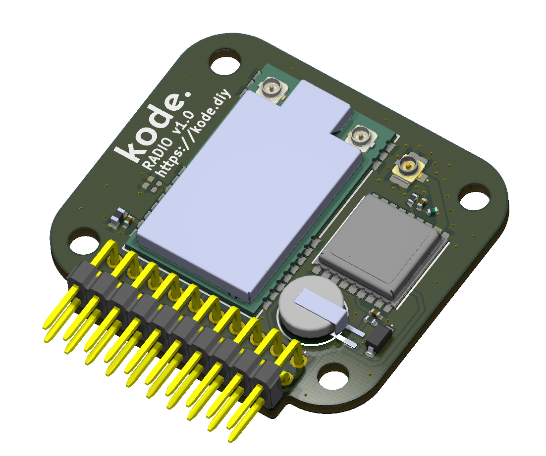
Con este módulo puedes desde **comunicarte con LoRa hasta ubicarte con GNSS.** Integra un módulo LoRa E80-900M2213S (LR1121) de Ebyte y un módulo GNSS MAX-M10S de U-Blox.
Estamos trabajando en la integración con **Meshtastic**.
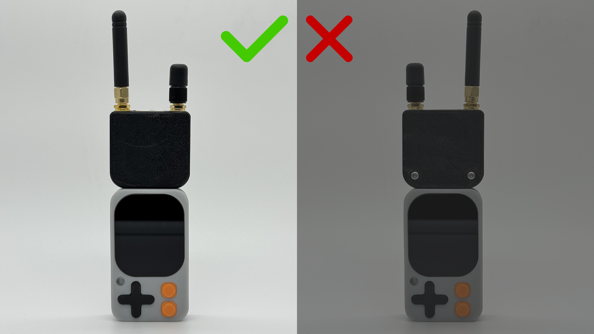
 ## Conexión con el Kode Dot
 ## Esquema de conexión
### Módulo LoRa
El módulo Ebyte E80-900M2213S está conectado al ESP32-S3 de la siguiente manera:
| E80-900M2213S | ESP32-S3 |
| ------------- | -------- |
| MISO | GPIO41 |
| MOSI | GPIO40 |
| SCK | GPIO39 |
| NSS (CS) | GPIO3 |
| BUSY | GPIO13 |
| LR\_NRESET | GPIO2 |
| DIO9 | GPIO12 |
| DIO8 | GPIO1 |
| DIO7 | GPIO11 |
### Módulo GNSS
El módulo GNSS MAX-M10S está conectado al ESP32-S3 de la siguiente manera:
| MAX-M10S | ESP32-S3 |
| -------- | -------- |
| TXD | GPIO44 |
| RXD | GPIO43 |
| SCL | GPIO47 |
| SDA | GPIO48 |
## Ejemplos de código
### Comunicación con LoRa
Para usar el módulo LoRa, recomendamos usar la librería [RadioLib](https://github.com/jgromes/RadioLib)
Este código es un ejemplo de cómo usar el módulo LoRa para escanear las bandas de 868 MHz y 2.4 GHz.
```cpp lora_test.ino lines icon="microchip" theme={null}
/**
* Escáner de canales LR1121 (solo RX, sin TX).
* Barre las bandas de 868 MHz y 2.4 GHz cambiando BW y SF dinámicamente.
* Mide el RSSI (ruido de canal) y muestra los resultados en formato CSV.
*/
/* ───────── KODE | docs.kode.diy ───────── */
#include
#include
/* Configuración de pines (según tu diseño) */
#define NSS_PIN 3 /* Chip Select */
#define DIO1_PIN 12 /* IRQ */
#define NRST_PIN 2 /* Reset */
#define BUSY_PIN 13 /* Busy */
#define MISO_PIN 41
#define MOSI_PIN 40
#define SCK_PIN 39
/* Mapeo del RF Switch para E80-900M2213S */
static const uint32_t rfswitch_dio_pins[] = {
RADIOLIB_LR11X0_DIO5, RADIOLIB_LR11X0_DIO6,
RADIOLIB_NC, RADIOLIB_NC, RADIOLIB_NC
};
static const Module::RfSwitchMode_t rfswitch_table[] = {
{ LR11x0::MODE_STBY, { LOW, LOW } },
{ LR11x0::MODE_RX, { LOW, LOW } }, /* RX */
{ LR11x0::MODE_TX, { LOW, HIGH } }, /* TX Sub-1GHz LP */
{ LR11x0::MODE_TX_HP, { HIGH, LOW } }, /* TX Sub-1GHz HP */
{ LR11x0::MODE_TX_HF, { HIGH, HIGH } }, /* TX 2.4GHz */
{ LR11x0::MODE_GNSS, { LOW, LOW } },
{ LR11x0::MODE_WIFI, { LOW, LOW } },
END_OF_MODE_TABLE,
};
/* Instancias */
SPIClass spi(HSPI);
LR1121 radio = new Module(NSS_PIN, DIO1_PIN, NRST_PIN, BUSY_PIN, spi);
/* Configuración de barrido de frecuencias */
const float FREQS_868[] = { 863.0, 866.0, 868.0, 869.5 };
const float FREQS_24[] = { 2403.5, 2425.0, 2450.0, 2479.5 };
const size_t N_868 = sizeof(FREQS_868) / sizeof(FREQS_868[0]);
const size_t N_24 = sizeof(FREQS_24) / sizeof(FREQS_24[0]);
/* Parámetros dinámicos */
const float BWS_KHZ[] = { 125.0, 203.125 };
const int SFS[] = { 7, 9, 12 };
const int CR = 5;
const int PWR_DBM = 10;
const uint8_t PREAMBLE = 8;
const float TCXO_V = 1.8;
/* Tiempo de escucha por punto de medida */
const uint16_t DWELL_MS = 200;
/* Funciones auxiliares */
/* Reset físico del LR1121 */
static void hardResetModule() {
pinMode(NRST_PIN, OUTPUT);
digitalWrite(NRST_PIN, LOW);
delay(50);
digitalWrite(NRST_PIN, HIGH);
delay(50);
}
/* Configura el LR1121 con los parámetros indicados */
static bool configRadio(float freqMHz, float bwkHz, int sf) {
int st = radio.begin(freqMHz, bwkHz, sf, CR, 0x12 /*sync*/, PWR_DBM, PREAMBLE, TCXO_V);
if (st != RADIOLIB_ERR_NONE) {
Serial.print("Fallo de configuración f="); Serial.print(freqMHz, 3);
Serial.print(" MHz BW="); Serial.print(bwkHz, 3);
Serial.print(" kHz SF="); Serial.print(sf);
Serial.print(" código="); Serial.println(st);
return false;
}
return true;
}
/* Mide una vez el RSSI con los parámetros indicados y muestra línea CSV */
static void measureOnce(float freqMHz, float bwkHz, int sf, const char* bandTag) {
if (!configRadio(freqMHz, bwkHz, sf)) return;
/* Iniciar recepción */
int st = radio.startReceive();
if (st != RADIOLIB_ERR_NONE) {
Serial.print("Fallo al iniciar RX, código="); Serial.println(st);
return;
}
delay(DWELL_MS);
float rssi = radio.getRSSI();
/* Salida en formato CSV: BANDA,FREQ_MHz,BW_kHz,SF,RSSI_dBm */
Serial.print(bandTag); Serial.print(",");
Serial.print(freqMHz, 3); Serial.print(",");
Serial.print(bwkHz, 3); Serial.print(",");
Serial.print(sf); Serial.print(",");
Serial.println(rssi, 1);
radio.standby();
}
/* Escanea toda una banda de frecuencias variando BW y SF */
static void scanBand(const float* freqs, size_t nFreq, const char* bandTag) {
Serial.println();
Serial.println("BANDA,FREQ_MHz,BW_kHz,SF,RSSI_dBm");
for (size_t i = 0; i < nFreq; i++) {
for (size_t b = 0; b < sizeof(BWS_KHZ)/sizeof(BWS_KHZ[0]); b++) {
for (size_t s = 0; s < sizeof(SFS)/sizeof(SFS[0]); s++) {
measureOnce(freqs[i], BWS_KHZ[b], SFS[s], bandTag);
}
}
}
}
/* Setup */
void setup() {
Serial.begin(115200);
while (!Serial) { delay(10); }
Serial.println("\n=== Escáner de canales LR1121 (solo RSSI) ===");
Serial.println("RSSI = ruido de canal (más cerca de 0 => más ruido)");
pinMode(BUSY_PIN, INPUT);
Serial.println("Reseteando módulo...");
hardResetModule();
Serial.println("Inicializando SPI...");
spi.begin(SCK_PIN, MISO_PIN, MOSI_PIN, NSS_PIN);
radio.setRfSwitchTable(rfswitch_dio_pins, rfswitch_table);
Serial.println("\n--- Escaneo: 868 MHz ---");
scanBand(FREQS_868, N_868, "868MHz");
Serial.println("\n--- Escaneo: 2.4 GHz ---");
scanBand(FREQS_24, N_24, "2400MHz");
Serial.println("\nFin del escaneo. Reinicia para repetir.");
}
/* Loop */
void loop() {
delay(1000);
}
```
### Ubicación con GNSS
Para usar el módulo GNSS, recomendamos usar la librería [SparkFun u-blox GNSS](https://github.com/sparkfun/SparkFun_u-blox_GNSS_v3)
#### Uso por I2C
Este código es un ejemplo de cómo usar el módulo GNSS por I2C.
```cpp gnss_test_I2C.ino lines icon="microchip" theme={null}
/**
* Ejemplo: Lectura de datos GNSS (GPS) desde un Módulo de Radio Kode vía I2C.
* Obtiene latitud, longitud y altitud del módulo u-blox.
* Utiliza el mensaje PVT (Posición, Velocidad, Tiempo) para la lectura de datos.
*/
/* ───────── KODE | docs.kode.diy ───────── */
#include
#include
/* Objeto del módulo GNSS */
SFE_UBLOX_GNSS myGNSS;
void setup()
{
Serial.begin(115200);
delay(1000);
Serial.println("Ejemplo de Módulo de Radio Kode");
/* ─── Inicializar I2C con SDA = GPIO48, SCL = GPIO47 ─── */
Wire.begin(48, 47);
/* Habilitar mensajes de depuración GNSS por Serial (opcional) */
myGNSS.enableDebugging(); // Comenta esta línea para desactivar mensajes de depuración
/* Intentar conectar con el módulo GNSS u-blox hasta que tenga éxito */
while (myGNSS.begin() == false)
{
Serial.println(F("u-blox GNSS no detectado. Reintentando..."));
delay(1000);
}
/* Configurar salida I2C en protocolo UBX únicamente (desactiva mensajes NMEA) */
myGNSS.setI2COutput(COM_TYPE_UBX);
}
void loop()
{
/* Si hay datos PVT disponibles, leerlos y mostrarlos */
if (myGNSS.getPVT() == true)
{
/* Obtener e imprimir latitud */
int32_t latitude = myGNSS.getLatitude();
Serial.print(F("Lat: "));
Serial.print(latitude);
/* Obtener e imprimir longitud */
int32_t longitude = myGNSS.getLongitude();
Serial.print(F(" Long: "));
Serial.print(longitude);
Serial.print(F(" (grados * 10^-7)"));
/* Obtener e imprimir altitud (MSL) */
int32_t altitude = myGNSS.getAltitudeMSL();
Serial.print(F(" Alt: "));
Serial.print(altitude);
Serial.print(F(" (mm)"));
Serial.println();
}
}
```
#### Uso por UART
Este código es un ejemplo de cómo usar el módulo GNSS por UART.
```cpp gnss_test_UART.ino lines icon="microchip" theme={null}
#include
/* Objeto GNSS para comunicación vía puerto serie */
SFE_UBLOX_GNSS_SERIAL myGNSS;
/* ─── Mapeo de pines para UART GNSS ───
* GNSS_RX_PIN → pin del MCU que recibe datos desde TX del GNSS
* GNSS_TX_PIN → pin del MCU que envía datos hacia RX del GNSS
*/
static const int GNSS_RX_PIN = 44; // MCU recibe por GPIO44
static const int GNSS_TX_PIN = 43; // MCU transmite por GPIO43
/* Instancia de puerto serie hardware (UART1) */
HardwareSerial GNSSSerial(1);
void setup()
{
Serial.begin(115200);
delay(1000);
Serial.println("u-blox GNSS vía UART1 (GPIO44/43)");
/* ─── Inicializar UART1 en los pines indicados ───
* Velocidad: 38400 baudios
* Formato: 8 bits, sin paridad, 1 bit de stop (SERIAL_8N1)
*/
GNSSSerial.begin(38400, SERIAL_8N1, GNSS_RX_PIN, GNSS_TX_PIN);
/* Activar mensajes de depuración en el puerto serie principal (opcional) */
myGNSS.enableDebugging(Serial);
/* Configurar salida de datos por UART1 → Solo protocolo UBX, sin NMEA */
myGNSS.setUART1Output(COM_TYPE_UBX);
/* Intentar conectar con el módulo GNSS hasta que responda */
while (!myGNSS.begin(GNSSSerial)) {
Serial.println(F("u-blox GNSS no detectado. Reintentando..."));
delay(1000);
}
}
void loop()
{
/* Si hay datos PVT (Posición, Velocidad, Tiempo) disponibles, mostrarlos */
if (myGNSS.getPVT()) {
int32_t lat = myGNSS.getLatitude(); // Latitud en grados * 10^-7
int32_t lon = myGNSS.getLongitude(); // Longitud en grados * 10^-7
int32_t alt = myGNSS.getAltitudeMSL(); // Altitud MSL en milímetros
Serial.print(F("Lat: ")); Serial.print(lat);
Serial.print(F(" Long: ")); Serial.print(lon);
Serial.print(F(" (deg*1e-7) Alt: ")); Serial.print(alt);
Serial.println(F(" (mm)"));
}
}
```
## Descarga de ejemplos
Puedes probar los códigos de ejemplo mediante el IDE de Arduino o el IDE de ESP-IDF o descargar los códigos en nuestro drive:
[Ejemplos de código del módulo Inventor](https://drive.google.com/drive/folders/1wom3hU-bjWmbpT9DnZFzFtpL3cr-7Qzg)
## Esquema de conexión
### Módulo LoRa
El módulo Ebyte E80-900M2213S está conectado al ESP32-S3 de la siguiente manera:
| E80-900M2213S | ESP32-S3 |
| ------------- | -------- |
| MISO | GPIO41 |
| MOSI | GPIO40 |
| SCK | GPIO39 |
| NSS (CS) | GPIO3 |
| BUSY | GPIO13 |
| LR\_NRESET | GPIO2 |
| DIO9 | GPIO12 |
| DIO8 | GPIO1 |
| DIO7 | GPIO11 |
### Módulo GNSS
El módulo GNSS MAX-M10S está conectado al ESP32-S3 de la siguiente manera:
| MAX-M10S | ESP32-S3 |
| -------- | -------- |
| TXD | GPIO44 |
| RXD | GPIO43 |
| SCL | GPIO47 |
| SDA | GPIO48 |
## Ejemplos de código
### Comunicación con LoRa
Para usar el módulo LoRa, recomendamos usar la librería [RadioLib](https://github.com/jgromes/RadioLib)
Este código es un ejemplo de cómo usar el módulo LoRa para escanear las bandas de 868 MHz y 2.4 GHz.
```cpp lora_test.ino lines icon="microchip" theme={null}
/**
* Escáner de canales LR1121 (solo RX, sin TX).
* Barre las bandas de 868 MHz y 2.4 GHz cambiando BW y SF dinámicamente.
* Mide el RSSI (ruido de canal) y muestra los resultados en formato CSV.
*/
/* ───────── KODE | docs.kode.diy ───────── */
#include
#include
/* Configuración de pines (según tu diseño) */
#define NSS_PIN 3 /* Chip Select */
#define DIO1_PIN 12 /* IRQ */
#define NRST_PIN 2 /* Reset */
#define BUSY_PIN 13 /* Busy */
#define MISO_PIN 41
#define MOSI_PIN 40
#define SCK_PIN 39
/* Mapeo del RF Switch para E80-900M2213S */
static const uint32_t rfswitch_dio_pins[] = {
RADIOLIB_LR11X0_DIO5, RADIOLIB_LR11X0_DIO6,
RADIOLIB_NC, RADIOLIB_NC, RADIOLIB_NC
};
static const Module::RfSwitchMode_t rfswitch_table[] = {
{ LR11x0::MODE_STBY, { LOW, LOW } },
{ LR11x0::MODE_RX, { LOW, LOW } }, /* RX */
{ LR11x0::MODE_TX, { LOW, HIGH } }, /* TX Sub-1GHz LP */
{ LR11x0::MODE_TX_HP, { HIGH, LOW } }, /* TX Sub-1GHz HP */
{ LR11x0::MODE_TX_HF, { HIGH, HIGH } }, /* TX 2.4GHz */
{ LR11x0::MODE_GNSS, { LOW, LOW } },
{ LR11x0::MODE_WIFI, { LOW, LOW } },
END_OF_MODE_TABLE,
};
/* Instancias */
SPIClass spi(HSPI);
LR1121 radio = new Module(NSS_PIN, DIO1_PIN, NRST_PIN, BUSY_PIN, spi);
/* Configuración de barrido de frecuencias */
const float FREQS_868[] = { 863.0, 866.0, 868.0, 869.5 };
const float FREQS_24[] = { 2403.5, 2425.0, 2450.0, 2479.5 };
const size_t N_868 = sizeof(FREQS_868) / sizeof(FREQS_868[0]);
const size_t N_24 = sizeof(FREQS_24) / sizeof(FREQS_24[0]);
/* Parámetros dinámicos */
const float BWS_KHZ[] = { 125.0, 203.125 };
const int SFS[] = { 7, 9, 12 };
const int CR = 5;
const int PWR_DBM = 10;
const uint8_t PREAMBLE = 8;
const float TCXO_V = 1.8;
/* Tiempo de escucha por punto de medida */
const uint16_t DWELL_MS = 200;
/* Funciones auxiliares */
/* Reset físico del LR1121 */
static void hardResetModule() {
pinMode(NRST_PIN, OUTPUT);
digitalWrite(NRST_PIN, LOW);
delay(50);
digitalWrite(NRST_PIN, HIGH);
delay(50);
}
/* Configura el LR1121 con los parámetros indicados */
static bool configRadio(float freqMHz, float bwkHz, int sf) {
int st = radio.begin(freqMHz, bwkHz, sf, CR, 0x12 /*sync*/, PWR_DBM, PREAMBLE, TCXO_V);
if (st != RADIOLIB_ERR_NONE) {
Serial.print("Fallo de configuración f="); Serial.print(freqMHz, 3);
Serial.print(" MHz BW="); Serial.print(bwkHz, 3);
Serial.print(" kHz SF="); Serial.print(sf);
Serial.print(" código="); Serial.println(st);
return false;
}
return true;
}
/* Mide una vez el RSSI con los parámetros indicados y muestra línea CSV */
static void measureOnce(float freqMHz, float bwkHz, int sf, const char* bandTag) {
if (!configRadio(freqMHz, bwkHz, sf)) return;
/* Iniciar recepción */
int st = radio.startReceive();
if (st != RADIOLIB_ERR_NONE) {
Serial.print("Fallo al iniciar RX, código="); Serial.println(st);
return;
}
delay(DWELL_MS);
float rssi = radio.getRSSI();
/* Salida en formato CSV: BANDA,FREQ_MHz,BW_kHz,SF,RSSI_dBm */
Serial.print(bandTag); Serial.print(",");
Serial.print(freqMHz, 3); Serial.print(",");
Serial.print(bwkHz, 3); Serial.print(",");
Serial.print(sf); Serial.print(",");
Serial.println(rssi, 1);
radio.standby();
}
/* Escanea toda una banda de frecuencias variando BW y SF */
static void scanBand(const float* freqs, size_t nFreq, const char* bandTag) {
Serial.println();
Serial.println("BANDA,FREQ_MHz,BW_kHz,SF,RSSI_dBm");
for (size_t i = 0; i < nFreq; i++) {
for (size_t b = 0; b < sizeof(BWS_KHZ)/sizeof(BWS_KHZ[0]); b++) {
for (size_t s = 0; s < sizeof(SFS)/sizeof(SFS[0]); s++) {
measureOnce(freqs[i], BWS_KHZ[b], SFS[s], bandTag);
}
}
}
}
/* Setup */
void setup() {
Serial.begin(115200);
while (!Serial) { delay(10); }
Serial.println("\n=== Escáner de canales LR1121 (solo RSSI) ===");
Serial.println("RSSI = ruido de canal (más cerca de 0 => más ruido)");
pinMode(BUSY_PIN, INPUT);
Serial.println("Reseteando módulo...");
hardResetModule();
Serial.println("Inicializando SPI...");
spi.begin(SCK_PIN, MISO_PIN, MOSI_PIN, NSS_PIN);
radio.setRfSwitchTable(rfswitch_dio_pins, rfswitch_table);
Serial.println("\n--- Escaneo: 868 MHz ---");
scanBand(FREQS_868, N_868, "868MHz");
Serial.println("\n--- Escaneo: 2.4 GHz ---");
scanBand(FREQS_24, N_24, "2400MHz");
Serial.println("\nFin del escaneo. Reinicia para repetir.");
}
/* Loop */
void loop() {
delay(1000);
}
```
### Ubicación con GNSS
Para usar el módulo GNSS, recomendamos usar la librería [SparkFun u-blox GNSS](https://github.com/sparkfun/SparkFun_u-blox_GNSS_v3)
#### Uso por I2C
Este código es un ejemplo de cómo usar el módulo GNSS por I2C.
```cpp gnss_test_I2C.ino lines icon="microchip" theme={null}
/**
* Ejemplo: Lectura de datos GNSS (GPS) desde un Módulo de Radio Kode vía I2C.
* Obtiene latitud, longitud y altitud del módulo u-blox.
* Utiliza el mensaje PVT (Posición, Velocidad, Tiempo) para la lectura de datos.
*/
/* ───────── KODE | docs.kode.diy ───────── */
#include
#include
/* Objeto del módulo GNSS */
SFE_UBLOX_GNSS myGNSS;
void setup()
{
Serial.begin(115200);
delay(1000);
Serial.println("Ejemplo de Módulo de Radio Kode");
/* ─── Inicializar I2C con SDA = GPIO48, SCL = GPIO47 ─── */
Wire.begin(48, 47);
/* Habilitar mensajes de depuración GNSS por Serial (opcional) */
myGNSS.enableDebugging(); // Comenta esta línea para desactivar mensajes de depuración
/* Intentar conectar con el módulo GNSS u-blox hasta que tenga éxito */
while (myGNSS.begin() == false)
{
Serial.println(F("u-blox GNSS no detectado. Reintentando..."));
delay(1000);
}
/* Configurar salida I2C en protocolo UBX únicamente (desactiva mensajes NMEA) */
myGNSS.setI2COutput(COM_TYPE_UBX);
}
void loop()
{
/* Si hay datos PVT disponibles, leerlos y mostrarlos */
if (myGNSS.getPVT() == true)
{
/* Obtener e imprimir latitud */
int32_t latitude = myGNSS.getLatitude();
Serial.print(F("Lat: "));
Serial.print(latitude);
/* Obtener e imprimir longitud */
int32_t longitude = myGNSS.getLongitude();
Serial.print(F(" Long: "));
Serial.print(longitude);
Serial.print(F(" (grados * 10^-7)"));
/* Obtener e imprimir altitud (MSL) */
int32_t altitude = myGNSS.getAltitudeMSL();
Serial.print(F(" Alt: "));
Serial.print(altitude);
Serial.print(F(" (mm)"));
Serial.println();
}
}
```
#### Uso por UART
Este código es un ejemplo de cómo usar el módulo GNSS por UART.
```cpp gnss_test_UART.ino lines icon="microchip" theme={null}
#include
/* Objeto GNSS para comunicación vía puerto serie */
SFE_UBLOX_GNSS_SERIAL myGNSS;
/* ─── Mapeo de pines para UART GNSS ───
* GNSS_RX_PIN → pin del MCU que recibe datos desde TX del GNSS
* GNSS_TX_PIN → pin del MCU que envía datos hacia RX del GNSS
*/
static const int GNSS_RX_PIN = 44; // MCU recibe por GPIO44
static const int GNSS_TX_PIN = 43; // MCU transmite por GPIO43
/* Instancia de puerto serie hardware (UART1) */
HardwareSerial GNSSSerial(1);
void setup()
{
Serial.begin(115200);
delay(1000);
Serial.println("u-blox GNSS vía UART1 (GPIO44/43)");
/* ─── Inicializar UART1 en los pines indicados ───
* Velocidad: 38400 baudios
* Formato: 8 bits, sin paridad, 1 bit de stop (SERIAL_8N1)
*/
GNSSSerial.begin(38400, SERIAL_8N1, GNSS_RX_PIN, GNSS_TX_PIN);
/* Activar mensajes de depuración en el puerto serie principal (opcional) */
myGNSS.enableDebugging(Serial);
/* Configurar salida de datos por UART1 → Solo protocolo UBX, sin NMEA */
myGNSS.setUART1Output(COM_TYPE_UBX);
/* Intentar conectar con el módulo GNSS hasta que responda */
while (!myGNSS.begin(GNSSSerial)) {
Serial.println(F("u-blox GNSS no detectado. Reintentando..."));
delay(1000);
}
}
void loop()
{
/* Si hay datos PVT (Posición, Velocidad, Tiempo) disponibles, mostrarlos */
if (myGNSS.getPVT()) {
int32_t lat = myGNSS.getLatitude(); // Latitud en grados * 10^-7
int32_t lon = myGNSS.getLongitude(); // Longitud en grados * 10^-7
int32_t alt = myGNSS.getAltitudeMSL(); // Altitud MSL en milímetros
Serial.print(F("Lat: ")); Serial.print(lat);
Serial.print(F(" Long: ")); Serial.print(lon);
Serial.print(F(" (deg*1e-7) Alt: ")); Serial.print(alt);
Serial.println(F(" (mm)"));
}
}
```
## Descarga de ejemplos
Puedes probar los códigos de ejemplo mediante el IDE de Arduino o el IDE de ESP-IDF o descargar los códigos en nuestro drive:
[Ejemplos de código del módulo Inventor](https://drive.google.com/drive/folders/1wom3hU-bjWmbpT9DnZFzFtpL3cr-7Qzg)