> ## Documentation Index
> Fetch the complete documentation index at: https://docs.kode.diy/llms.txt
> Use this file to discover all available pages before exploring further.
# Inventor
> Connect motors DC, a servo motor and sensors to create your own robot.
**Module:** Basic
# Features
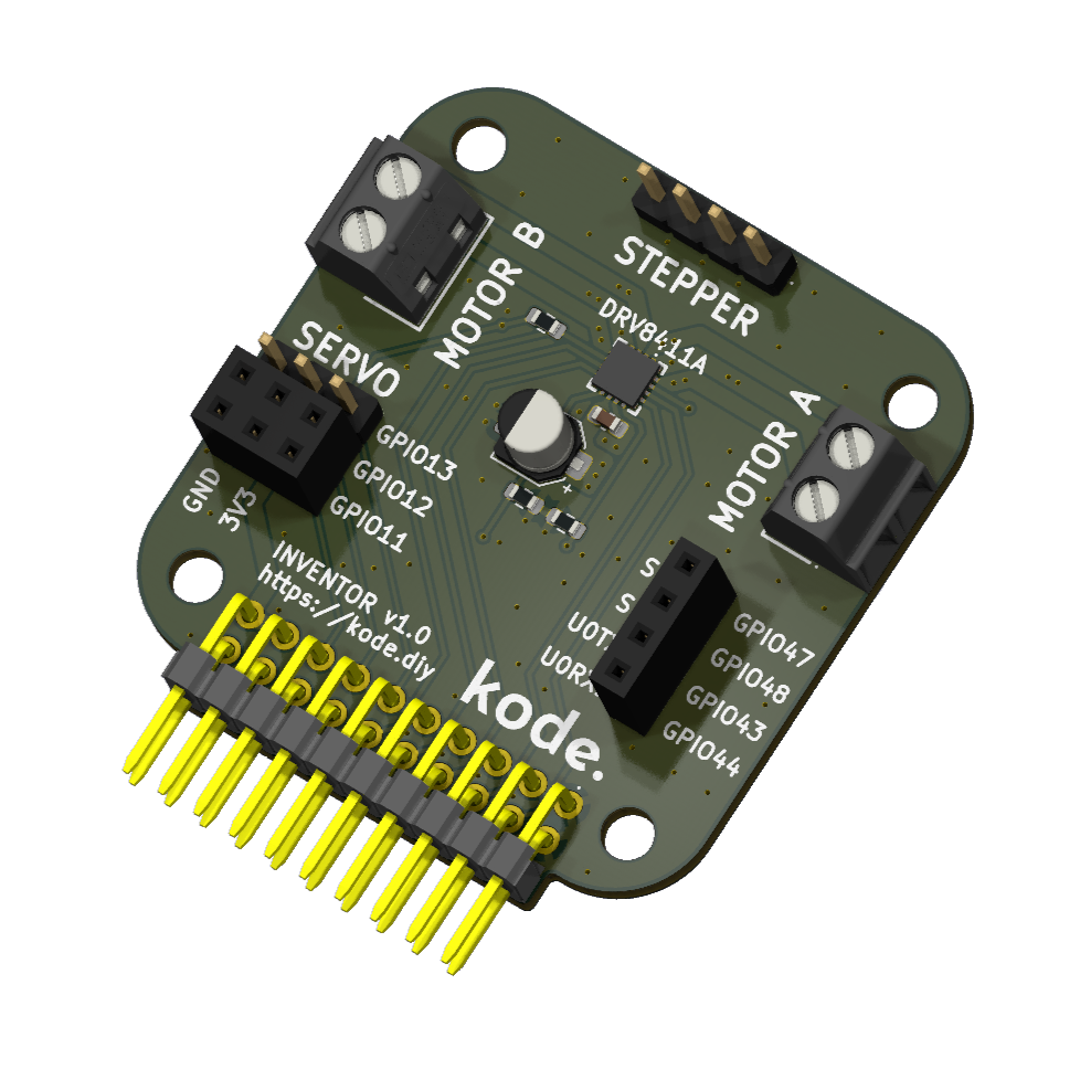
With this module you can connect **motors to your Kode Dot and make robots like a car following lines.**
You can connect the following:
* 2x DC motors or 1x stepper motor
* 1x servo motor
* 4x GPIOs for sensors
* 1x I2C bus
It is not necessary to use an external power supply because **everything is powered from the Kode Dot.**
The **DC motors have to be 5V and are limited by hardware to a current of 700mA per motor.** So, as the Kode Dot can supply up to 2A, there are **600mA left to connect a servo motor.**
The **DC motors are controlled by PWM** and you can measure the current that each motor is consuming to have an estimation of its torque.
 ## Connection scheme
The driver that controls the motors is connected as follows:
| Driver | ESP32-S3 |
| ------- | -------- |
| AIN1 | GPIO42 |
| AIN2 | GPIO41 |
| BIN1 | GPIO40 |
| BIN2 | GPIO39 |
| nFAULT | GPIO38 |
| AIPROPI | GPIO37 |
| BIPROPI | GPIO36 |
AIPROPI and BIPROPI are used to measure the current that each motor is consuming. For more information, consult the driver's datasheet.
## Example code
Connect **two DC motors to the connectors** and with this code you will see how they first accelerate, then maintain the maximum speed and finally decelerate.
```cpp motors_test.ino lines icon="microchip" theme={null}
/**
* DRV8411A + 2x DC + Servo + Current reading via IPROPI (ESP32-S3).
* Prints to Serial Plotter: IA(A) \t IB(A) \t ITRIP(A) while sequencing both motors and a servo.
* IPROPI math (datasheet): IPROPI(µA) = I_LS_total(A) * 200 µA/A; V_IPROPI = IPROPI * R_IPROPI;
* I_motor = V_IPROPI / (R_IPROPI * 200e-6); I_TRIP = VREF / (R_IPROPI * 200e-6).
*/
/* ───────── KODE | docs.kode.diy ───────── */
#include
#include
/* DRV8411A pins */
constexpr int PIN_AIN1 = 42;
constexpr int PIN_AIN2 = 41;
constexpr int PIN_BIN1 = 39;
constexpr int PIN_BIN2 = 40;
constexpr int PIN_nFAULT = 3;
/* IPROPI -> ADC (A channel and B channel) */
constexpr int PIN_AIPROPI = 2; /* ADC input for A-IPROPI */
constexpr int PIN_BIPROPI = 1; /* ADC input for B-IPROPI */
/* Servo */
constexpr int PIN_SERVO = 13;
Servo servo;
/* Servo settings (microseconds and angles) */
constexpr int SERVO_MIN_US = 500;
constexpr int SERVO_MAX_US = 2500;
constexpr int SERVO_CENTER = 90;
constexpr int SERVO_LEFT = 0;
constexpr int SERVO_RIGHT = 180;
/* DRV8411A helpers */
inline void motorA_coast() { digitalWrite(PIN_AIN1, LOW); digitalWrite(PIN_AIN2, LOW); } /* Hi-Z both inputs */
inline void motorA_brake() { digitalWrite(PIN_AIN1, HIGH); digitalWrite(PIN_AIN2, HIGH); } /* Fast decay brake */
inline void motorA_fwd() { digitalWrite(PIN_AIN1, HIGH); digitalWrite(PIN_AIN2, LOW); } /* A forward */
inline void motorA_rev() { digitalWrite(PIN_AIN1, LOW); digitalWrite(PIN_AIN2, HIGH); } /* A reverse */
inline void motorB_coast() { digitalWrite(PIN_BIN1, LOW); digitalWrite(PIN_BIN2, LOW); } /* Hi-Z both inputs */
inline void motorB_brake() { digitalWrite(PIN_BIN1, HIGH); digitalWrite(PIN_BIN2, HIGH); } /* Fast decay brake */
inline void motorB_fwd() { digitalWrite(PIN_BIN1, HIGH); digitalWrite(PIN_BIN2, LOW); } /* B forward */
inline void motorB_rev() { digitalWrite(PIN_BIN1, LOW); digitalWrite(PIN_BIN2, HIGH); } /* B reverse */
/* Timings */
constexpr uint32_t T_MOTOR_DIR = 2000; /* 2 s per direction */
constexpr uint32_t T_SERVO_TRAMO = 1000; /* 1 s per segment */
/* IPROPI parameters (set R to your actual resistor!) */
constexpr float VREF_V = 3.3f; /* VREF (V) */
constexpr float RIPROPI_OHMS = 23700.0f; /* Change to 10000.0f if you use 10 kΩ */
constexpr float AIPROPI_GAIN = 200e-6f; /* 200 µA/A (IPROPI gain) */
/* ADC configuration */
constexpr int ADC_BITS = 12; /* ADC resolution */
constexpr float ADC_VFULL = 3.3f; /* With 11 dB attenuation, ~3.3 V full scale */
/* Concurrent state machines */
enum class Phase { FWD, REV, DONE };
struct MotorSeq {
bool enabled=false; Phase phase=Phase::FWD; uint32_t tEnd=0;
void start() { enabled=true; phase=Phase::FWD; tEnd=millis()+T_MOTOR_DIR; }
};
struct ServoSeq {
bool enabled=false; int step=0; uint32_t tEnd=0;
void start() { enabled=true; step=0; servo.write(SERVO_RIGHT); tEnd=millis()+T_SERVO_TRAMO; }
};
MotorSeq seqA, seqB; ServoSeq seqS;
/* ADC counts -> volts */
float adcVolts(int pin) {
uint16_t raw = analogRead(pin);
return (raw * ADC_VFULL) / ((1 << ADC_BITS) - 1);
}
/* IPROPI volts -> motor current (A) */
float ipropiToCurrentA(float v_ipropi) {
return v_ipropi / (RIPROPI_OHMS * AIPROPI_GAIN);
}
/* Periodic sampling to Serial Plotter: IA, IB, and ITRIP */
void sampleAndPrintCurrents() {
float vA = adcVolts(PIN_AIPROPI);
float vB = adcVolts(PIN_BIPROPI);
float iA = ipropiToCurrentA(vA);
float iB = ipropiToCurrentA(vB);
float iTRIP = VREF_V / (RIPROPI_OHMS * AIPROPI_GAIN); /* Overcurrent trip threshold (A) */
/* Tab-separated columns for Arduino Serial Plotter */
Serial.print(iA, 4); Serial.print('\t');
Serial.print(iB, 4); Serial.print('\t');
Serial.println(iTRIP, 4);
}
/* Busy wait with periodic sampling (~every 20 ms) */
void waitWithSampling(uint32_t ms) {
uint32_t t0 = millis(), tNext = 0;
while ((uint32_t)(millis() - t0) < ms) {
uint32_t now = millis();
if ((int32_t)(now - tNext) >= 0) {
sampleAndPrintCurrents();
tNext = now + 20;
}
delay(1); /* Yield briefly */
}
}
/* Check /nFAULT low during a tagged section */
void checkFault(const char* tag) {
if (digitalRead(PIN_nFAULT) == LOW) {
Serial.print("[nFAULT] Fault detected during ");
Serial.println(tag);
}
}
void setup() {
Serial.begin(115200);
delay(100);
pinMode(PIN_AIN1, OUTPUT);
pinMode(PIN_AIN2, OUTPUT);
pinMode(PIN_BIN1, OUTPUT);
pinMode(PIN_BIN2, OUTPUT);
pinMode(PIN_nFAULT, INPUT_PULLUP);
motorA_coast();
motorB_coast();
/* ADC: 11 dB to cover up to ~3.3 V and 12-bit resolution */
analogReadResolution(ADC_BITS);
analogSetAttenuation(ADC_11db);
/* Optional header for Serial Plotter */
Serial.println("IA(A)\tIB(A)\tITRIP(A)");
/* Servo setup (50 Hz, constrained to given pulse widths) */
servo.setPeriodHertz(50);
servo.attach(PIN_SERVO, SERVO_MIN_US, SERVO_MAX_US);
servo.write(SERVO_CENTER);
/* 1) Motor A forward then reverse with sampling */
motorA_fwd(); waitWithSampling(T_MOTOR_DIR);
motorA_rev(); waitWithSampling(T_MOTOR_DIR);
motorA_brake(); delay(100); motorA_coast();
checkFault("Sequence 1 (Motor A)");
/* 2) Motor B forward then reverse with sampling */
motorB_fwd(); waitWithSampling(T_MOTOR_DIR);
motorB_rev(); waitWithSampling(T_MOTOR_DIR);
motorB_brake(); delay(100); motorB_coast();
checkFault("Sequence 2 (Motor B)");
/* 3) Servo sweep: +90°, -90° (1 s each segment) */
servo.write(SERVO_RIGHT); waitWithSampling(T_SERVO_TRAMO);
servo.write(SERVO_LEFT); waitWithSampling(T_SERVO_TRAMO);
servo.write(SERVO_CENTER);
/* 4) Concurrent sequences */
seqA.start(); seqB.start(); seqS.start();
}
void loop() {
/* Continuous sampling for the Plotter (~50 Hz) */
static uint32_t tNext = 0;
uint32_t now = millis();
if ((int32_t)(now - tNext) >= 0) {
sampleAndPrintCurrents();
tNext = now + 20;
}
/* Motor A concurrent sequence */
if (seqA.enabled) {
if (seqA.phase == Phase::FWD) {
motorA_fwd();
if ((int32_t)(now - seqA.tEnd) >= 0) {
seqA.phase = Phase::REV;
seqA.tEnd = now + T_MOTOR_DIR;
}
} else if (seqA.phase == Phase::REV) {
motorA_rev();
if ((int32_t)(now - seqA.tEnd) >= 0) {
seqA.phase = Phase::DONE; motorA_brake(); delay(50); motorA_coast();
}
}
}
/* Motor B concurrent sequence */
if (seqB.enabled) {
if (seqB.phase == Phase::FWD) {
motorB_fwd();
if ((int32_t)(now - seqB.tEnd) >= 0) {
seqB.phase = Phase::REV;
seqB.tEnd = now + T_MOTOR_DIR;
}
} else if (seqB.phase == Phase::REV) {
motorB_rev();
if ((int32_t)(now - seqB.tEnd) >= 0) {
seqB.phase = Phase::DONE; motorB_brake(); delay(50); motorB_coast();
}
}
}
/* Servo concurrent sequence (RIGHT -> LEFT -> CENTER) */
if (seqS.enabled) {
if (seqS.step == 0) {
if ((int32_t)(now - seqS.tEnd) >= 0) {
servo.write(SERVO_LEFT);
seqS.step = 1; seqS.tEnd = now + T_SERVO_TRAMO;
}
} else if (seqS.step == 1) {
if ((int32_t)(now - seqS.tEnd) >= 0) {
servo.write(SERVO_CENTER);
seqS.step = 2;
}
}
}
/* End condition: both motors done and servo centered */
if (seqA.phase == Phase::DONE && seqB.phase == Phase::DONE && seqS.step == 2) {
checkFault("Sequence 4 (concurrent)");
seqA.enabled = seqB.enabled = false; seqS.enabled = false;
motorA_coast(); motorB_coast();
while (true) { delay(1000); } /* Hold here after completion */
}
}
```
## Download examples
You can test the example codes using the Arduino IDE or the ESP-IDF IDE or download the codes in our drive:
[Example codes of the Inventor module](https://drive.google.com/drive/folders/1wom3hU-bjWmbpT9DnZFzFtpL3cr-7Qzg)
## Connection scheme
The driver that controls the motors is connected as follows:
| Driver | ESP32-S3 |
| ------- | -------- |
| AIN1 | GPIO42 |
| AIN2 | GPIO41 |
| BIN1 | GPIO40 |
| BIN2 | GPIO39 |
| nFAULT | GPIO38 |
| AIPROPI | GPIO37 |
| BIPROPI | GPIO36 |
AIPROPI and BIPROPI are used to measure the current that each motor is consuming. For more information, consult the driver's datasheet.
## Example code
Connect **two DC motors to the connectors** and with this code you will see how they first accelerate, then maintain the maximum speed and finally decelerate.
```cpp motors_test.ino lines icon="microchip" theme={null}
/**
* DRV8411A + 2x DC + Servo + Current reading via IPROPI (ESP32-S3).
* Prints to Serial Plotter: IA(A) \t IB(A) \t ITRIP(A) while sequencing both motors and a servo.
* IPROPI math (datasheet): IPROPI(µA) = I_LS_total(A) * 200 µA/A; V_IPROPI = IPROPI * R_IPROPI;
* I_motor = V_IPROPI / (R_IPROPI * 200e-6); I_TRIP = VREF / (R_IPROPI * 200e-6).
*/
/* ───────── KODE | docs.kode.diy ───────── */
#include
#include
/* DRV8411A pins */
constexpr int PIN_AIN1 = 42;
constexpr int PIN_AIN2 = 41;
constexpr int PIN_BIN1 = 39;
constexpr int PIN_BIN2 = 40;
constexpr int PIN_nFAULT = 3;
/* IPROPI -> ADC (A channel and B channel) */
constexpr int PIN_AIPROPI = 2; /* ADC input for A-IPROPI */
constexpr int PIN_BIPROPI = 1; /* ADC input for B-IPROPI */
/* Servo */
constexpr int PIN_SERVO = 13;
Servo servo;
/* Servo settings (microseconds and angles) */
constexpr int SERVO_MIN_US = 500;
constexpr int SERVO_MAX_US = 2500;
constexpr int SERVO_CENTER = 90;
constexpr int SERVO_LEFT = 0;
constexpr int SERVO_RIGHT = 180;
/* DRV8411A helpers */
inline void motorA_coast() { digitalWrite(PIN_AIN1, LOW); digitalWrite(PIN_AIN2, LOW); } /* Hi-Z both inputs */
inline void motorA_brake() { digitalWrite(PIN_AIN1, HIGH); digitalWrite(PIN_AIN2, HIGH); } /* Fast decay brake */
inline void motorA_fwd() { digitalWrite(PIN_AIN1, HIGH); digitalWrite(PIN_AIN2, LOW); } /* A forward */
inline void motorA_rev() { digitalWrite(PIN_AIN1, LOW); digitalWrite(PIN_AIN2, HIGH); } /* A reverse */
inline void motorB_coast() { digitalWrite(PIN_BIN1, LOW); digitalWrite(PIN_BIN2, LOW); } /* Hi-Z both inputs */
inline void motorB_brake() { digitalWrite(PIN_BIN1, HIGH); digitalWrite(PIN_BIN2, HIGH); } /* Fast decay brake */
inline void motorB_fwd() { digitalWrite(PIN_BIN1, HIGH); digitalWrite(PIN_BIN2, LOW); } /* B forward */
inline void motorB_rev() { digitalWrite(PIN_BIN1, LOW); digitalWrite(PIN_BIN2, HIGH); } /* B reverse */
/* Timings */
constexpr uint32_t T_MOTOR_DIR = 2000; /* 2 s per direction */
constexpr uint32_t T_SERVO_TRAMO = 1000; /* 1 s per segment */
/* IPROPI parameters (set R to your actual resistor!) */
constexpr float VREF_V = 3.3f; /* VREF (V) */
constexpr float RIPROPI_OHMS = 23700.0f; /* Change to 10000.0f if you use 10 kΩ */
constexpr float AIPROPI_GAIN = 200e-6f; /* 200 µA/A (IPROPI gain) */
/* ADC configuration */
constexpr int ADC_BITS = 12; /* ADC resolution */
constexpr float ADC_VFULL = 3.3f; /* With 11 dB attenuation, ~3.3 V full scale */
/* Concurrent state machines */
enum class Phase { FWD, REV, DONE };
struct MotorSeq {
bool enabled=false; Phase phase=Phase::FWD; uint32_t tEnd=0;
void start() { enabled=true; phase=Phase::FWD; tEnd=millis()+T_MOTOR_DIR; }
};
struct ServoSeq {
bool enabled=false; int step=0; uint32_t tEnd=0;
void start() { enabled=true; step=0; servo.write(SERVO_RIGHT); tEnd=millis()+T_SERVO_TRAMO; }
};
MotorSeq seqA, seqB; ServoSeq seqS;
/* ADC counts -> volts */
float adcVolts(int pin) {
uint16_t raw = analogRead(pin);
return (raw * ADC_VFULL) / ((1 << ADC_BITS) - 1);
}
/* IPROPI volts -> motor current (A) */
float ipropiToCurrentA(float v_ipropi) {
return v_ipropi / (RIPROPI_OHMS * AIPROPI_GAIN);
}
/* Periodic sampling to Serial Plotter: IA, IB, and ITRIP */
void sampleAndPrintCurrents() {
float vA = adcVolts(PIN_AIPROPI);
float vB = adcVolts(PIN_BIPROPI);
float iA = ipropiToCurrentA(vA);
float iB = ipropiToCurrentA(vB);
float iTRIP = VREF_V / (RIPROPI_OHMS * AIPROPI_GAIN); /* Overcurrent trip threshold (A) */
/* Tab-separated columns for Arduino Serial Plotter */
Serial.print(iA, 4); Serial.print('\t');
Serial.print(iB, 4); Serial.print('\t');
Serial.println(iTRIP, 4);
}
/* Busy wait with periodic sampling (~every 20 ms) */
void waitWithSampling(uint32_t ms) {
uint32_t t0 = millis(), tNext = 0;
while ((uint32_t)(millis() - t0) < ms) {
uint32_t now = millis();
if ((int32_t)(now - tNext) >= 0) {
sampleAndPrintCurrents();
tNext = now + 20;
}
delay(1); /* Yield briefly */
}
}
/* Check /nFAULT low during a tagged section */
void checkFault(const char* tag) {
if (digitalRead(PIN_nFAULT) == LOW) {
Serial.print("[nFAULT] Fault detected during ");
Serial.println(tag);
}
}
void setup() {
Serial.begin(115200);
delay(100);
pinMode(PIN_AIN1, OUTPUT);
pinMode(PIN_AIN2, OUTPUT);
pinMode(PIN_BIN1, OUTPUT);
pinMode(PIN_BIN2, OUTPUT);
pinMode(PIN_nFAULT, INPUT_PULLUP);
motorA_coast();
motorB_coast();
/* ADC: 11 dB to cover up to ~3.3 V and 12-bit resolution */
analogReadResolution(ADC_BITS);
analogSetAttenuation(ADC_11db);
/* Optional header for Serial Plotter */
Serial.println("IA(A)\tIB(A)\tITRIP(A)");
/* Servo setup (50 Hz, constrained to given pulse widths) */
servo.setPeriodHertz(50);
servo.attach(PIN_SERVO, SERVO_MIN_US, SERVO_MAX_US);
servo.write(SERVO_CENTER);
/* 1) Motor A forward then reverse with sampling */
motorA_fwd(); waitWithSampling(T_MOTOR_DIR);
motorA_rev(); waitWithSampling(T_MOTOR_DIR);
motorA_brake(); delay(100); motorA_coast();
checkFault("Sequence 1 (Motor A)");
/* 2) Motor B forward then reverse with sampling */
motorB_fwd(); waitWithSampling(T_MOTOR_DIR);
motorB_rev(); waitWithSampling(T_MOTOR_DIR);
motorB_brake(); delay(100); motorB_coast();
checkFault("Sequence 2 (Motor B)");
/* 3) Servo sweep: +90°, -90° (1 s each segment) */
servo.write(SERVO_RIGHT); waitWithSampling(T_SERVO_TRAMO);
servo.write(SERVO_LEFT); waitWithSampling(T_SERVO_TRAMO);
servo.write(SERVO_CENTER);
/* 4) Concurrent sequences */
seqA.start(); seqB.start(); seqS.start();
}
void loop() {
/* Continuous sampling for the Plotter (~50 Hz) */
static uint32_t tNext = 0;
uint32_t now = millis();
if ((int32_t)(now - tNext) >= 0) {
sampleAndPrintCurrents();
tNext = now + 20;
}
/* Motor A concurrent sequence */
if (seqA.enabled) {
if (seqA.phase == Phase::FWD) {
motorA_fwd();
if ((int32_t)(now - seqA.tEnd) >= 0) {
seqA.phase = Phase::REV;
seqA.tEnd = now + T_MOTOR_DIR;
}
} else if (seqA.phase == Phase::REV) {
motorA_rev();
if ((int32_t)(now - seqA.tEnd) >= 0) {
seqA.phase = Phase::DONE; motorA_brake(); delay(50); motorA_coast();
}
}
}
/* Motor B concurrent sequence */
if (seqB.enabled) {
if (seqB.phase == Phase::FWD) {
motorB_fwd();
if ((int32_t)(now - seqB.tEnd) >= 0) {
seqB.phase = Phase::REV;
seqB.tEnd = now + T_MOTOR_DIR;
}
} else if (seqB.phase == Phase::REV) {
motorB_rev();
if ((int32_t)(now - seqB.tEnd) >= 0) {
seqB.phase = Phase::DONE; motorB_brake(); delay(50); motorB_coast();
}
}
}
/* Servo concurrent sequence (RIGHT -> LEFT -> CENTER) */
if (seqS.enabled) {
if (seqS.step == 0) {
if ((int32_t)(now - seqS.tEnd) >= 0) {
servo.write(SERVO_LEFT);
seqS.step = 1; seqS.tEnd = now + T_SERVO_TRAMO;
}
} else if (seqS.step == 1) {
if ((int32_t)(now - seqS.tEnd) >= 0) {
servo.write(SERVO_CENTER);
seqS.step = 2;
}
}
}
/* End condition: both motors done and servo centered */
if (seqA.phase == Phase::DONE && seqB.phase == Phase::DONE && seqS.step == 2) {
checkFault("Sequence 4 (concurrent)");
seqA.enabled = seqB.enabled = false; seqS.enabled = false;
motorA_coast(); motorB_coast();
while (true) { delay(1000); } /* Hold here after completion */
}
}
```
## Download examples
You can test the example codes using the Arduino IDE or the ESP-IDF IDE or download the codes in our drive:
[Example codes of the Inventor module](https://drive.google.com/drive/folders/1wom3hU-bjWmbpT9DnZFzFtpL3cr-7Qzg)